S120 Combi Power Modules
4.3 Interface description
SINAMICS S120 Combi
74 Manual, 11/2017, 6SL3097-4AV00-0BP7
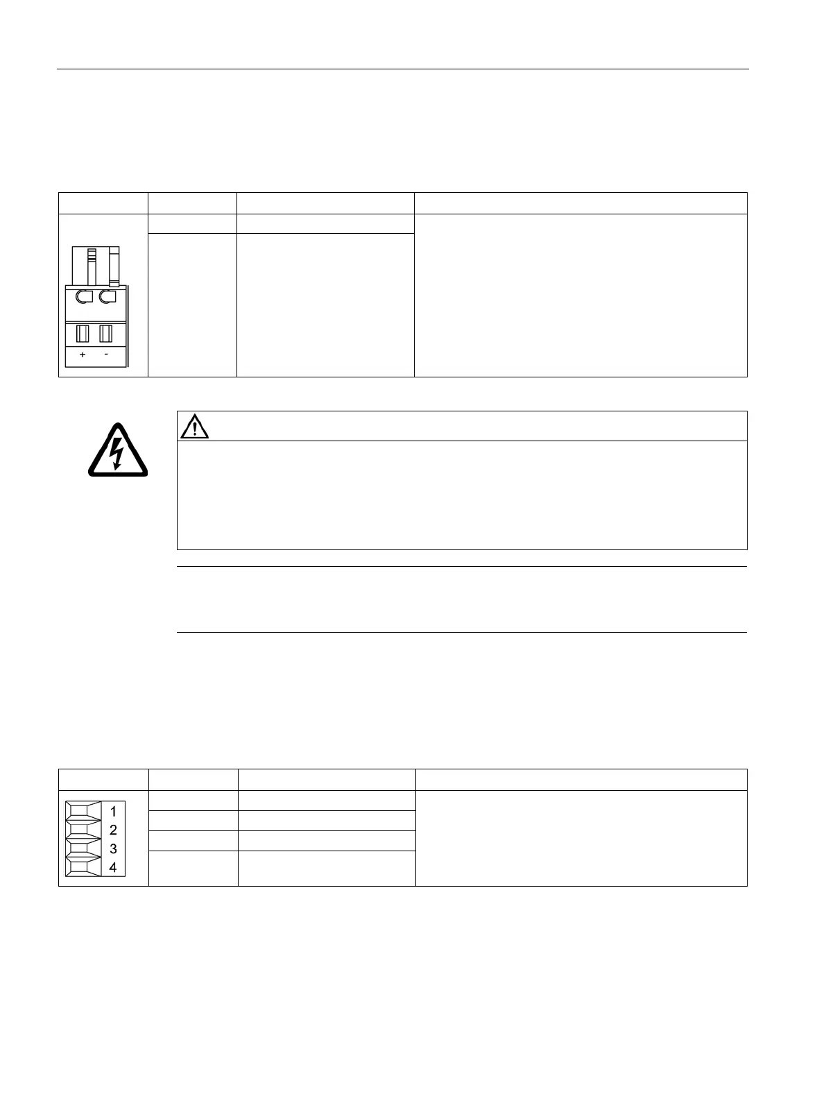
Table 4- 8 Brake connection X11
Connectors:
Voltage: 24 VDC
Max. load current: 1 A
Minimum load current: 0.1 A
Type: Spring-loaded terminal 1 (Page 288)
The brake connector is part of the prefabricated cable.
BR - Brake connection -
Electric shock due to a terminal voltage that has not been adjusted
Contact with live terminals can cause death or severe injury.
• Only connect protective extra-low voltages (PELV or SELV) to all connections and
terminals between 0 and 48 VDC.
• Observe the voltage tolerances of the motor holding brakes (24 V ± 10%).
Note
The motor brake must be connected via connector X11. The BR
- cable must not be
connected directly to electronics ground (M).
Table 4- 9 X12/X13 connection of the external fan unit
Current-carrying capacity (24 V): 2 x 1 A or 1 x 2 A
Type: Screw terminal 1 (Page 288)
4 Ground

 Loading...


