Additional system components
9.1 Terminal Module TM54F
SINAMICS S120 Combi
204 Manual, 11/2017, 6SL3097-4AV00-0BP7
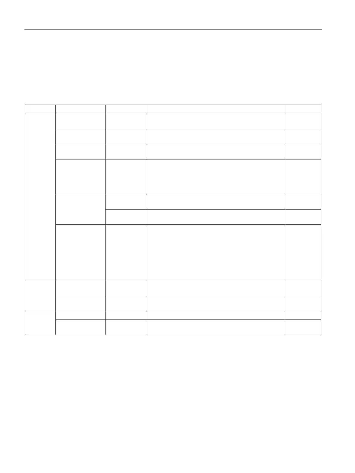
Meaning of the LEDs on the Terminal Module TM54F
Table 9- 14 Meaning of the LEDs on the Terminal Module TM54F
READY - Off The electronics power supply is missing or outside the
permissible tolerance range.
–
Green Continuous
light
The component is ready for operation, cyclic DRIVE-
CLiQ communication is taking place.
–
Orange Continuous
DRIVE-CLiQ communication is being established. –
Red Continuous
light
This component has at least one fault.
The LED is activated irrespective of whether the corre-
sponding messages have been reconfigured.
Remedy and
acknowledge
fault or safely
acknowledge
Green / Red Flashing light
Firmware is being downloaded. –
Flashing light 2
Firmware download is complete. Wait for POWER ON. Carry out a
Green / Orange
or
Red / Orange
Flashing light 1
Hz
Component recognition via LED is activated
(p0154 = 1).
Both options depend on the LED status when compo-
nent recognition is activated.
Green / Orange: Component is operating without any
faults
Red/orange: Component signals a fault
–
L1+, L2+ – Off The controllable sensor power supply is functioning
–
Red Continuous
There is a fault in the controllable sensor power supply. –
L3+
The sensor power supply is operating fault-free.
Red Continuous
The sensor power supply has a fault. –

 Loading...


