EasyManuals Logo

Siemens SINAMICS S120 Combi User Manual

Siemens SINAMICS S120 Combi
330 pages
To Next Page IconTo Next Page
To Previous Page IconTo Previous Page
Page #260 background imageLoading...
Page #260 background image
Encoder system connection
10.4 Sensor Module External SME25
SINAMICS S120 Combi
260 Manual, 11/2017, 6SL3097-4AV00-0BP7
10.4.5
Installation
â‘ 
Contact surface
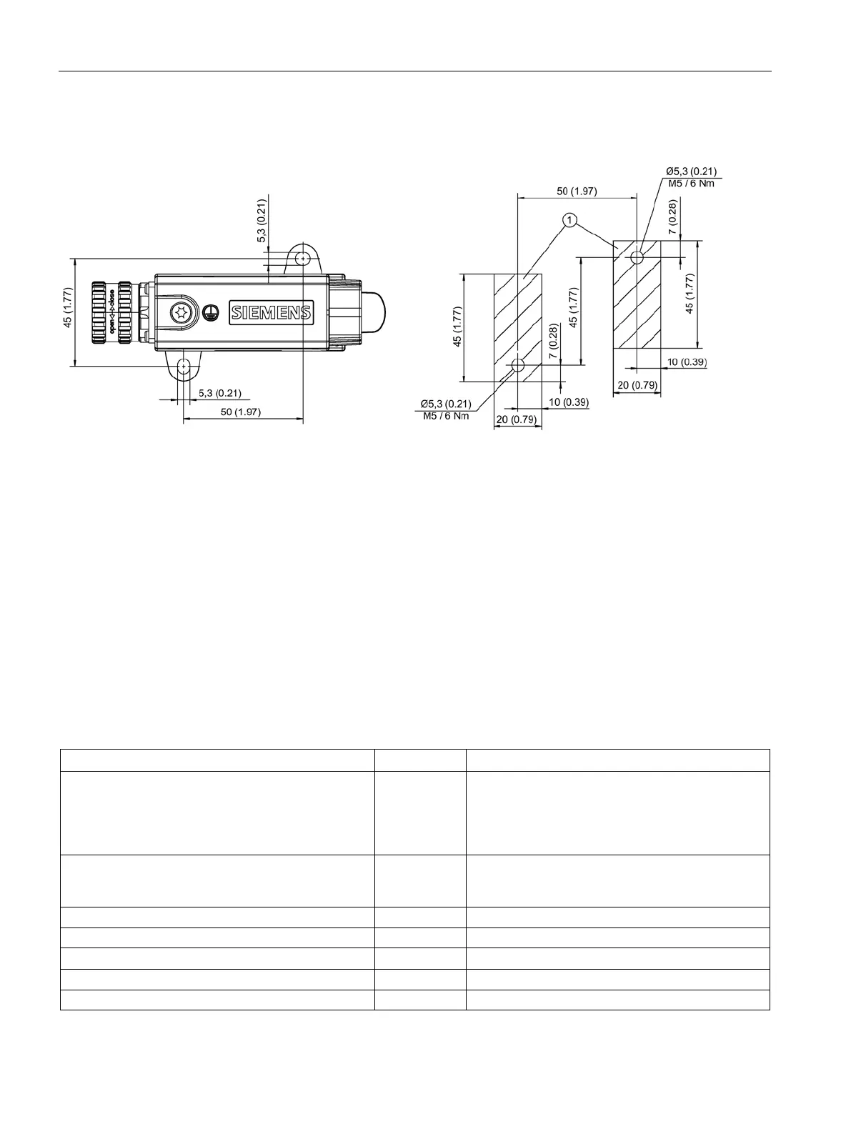
Figure 10-21 Drilling pattern for installing the SME20/SME25
Installation
1. Place the drilling pattern on the mounting surface. Make sure that the contact surface is
bare, unpainted metal.
2. Drill two holes with Ø 5.3 or M5 threaded holes according to the drilling pattern.
3. Fix the Sensor Module to the mounting surface. The tightening torque is 6 Nm.
10.4.6
Technical data
Table 10- 20 Technical data
6SL3055-0AA00-5HA3
Unit
Value
Electronics power supply
Voltage
Current (without encoder system)
Current (with encoder system)
Power loss
V
DC
A
DC
A
DC
W
24 (20.4 … 28.8)
≤ 0.15
≤ 0.25
≤ 4
Encoder system power supply
Voltage
Current
V
DC
A
DC
5
0.35
Encoder frequency that can be evaluated (f
encoder
)
kHz
≤ 500
SSI/EnDat 2.1 baud rate
kHz
100
PE/ground connection
At the housing with M4 / 1.8 Nm screw
Weight
kg
0.31
Degree of protection
IP67

Table of Contents

Other manuals for Siemens SINAMICS S120 Combi

Questions and Answers:

Question and Answer IconNeed help?

Do you have a question about the Siemens SINAMICS S120 Combi and is the answer not in the manual?

Siemens SINAMICS S120 Combi Specifications

General IconGeneral
BrandSiemens
ModelSINAMICS S120 Combi
CategoryControl Unit
LanguageEnglish

Related product manuals