Additional system components
9.1 Terminal Module TM54F
SINAMICS S120 Combi
Manual, 11/2017, 6SL3097-4AV00-0BP7
195
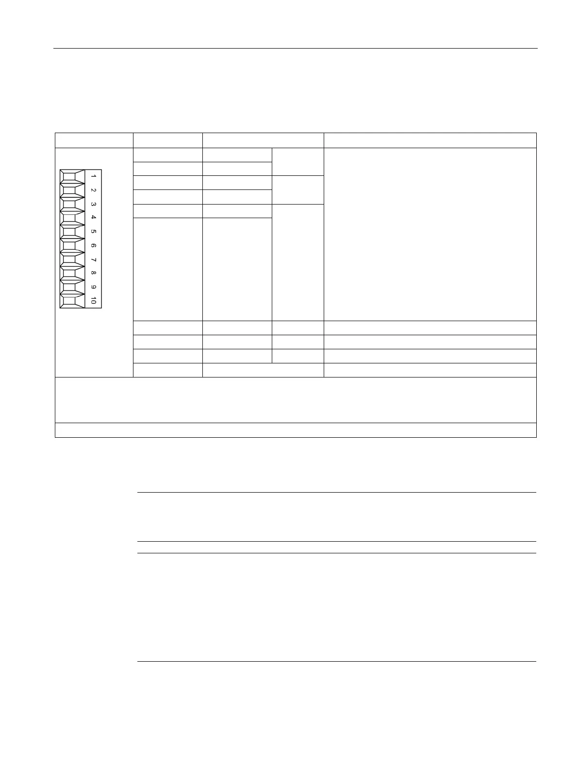
X522 fail-safe digital inputs
Table 9- 6 X522: Fail-safe digital inputs
F-DI 2 Voltage: -3 … +30 VDC
Electrical isolation: Yes
Reference potential: see terminals 7, 8, 9, 10
Input characteristic acc. to IEC 61131-2, type 1
Input voltage (including ripple)
"1" signal: 15 … 30 V
"0" signal: -3 … +5 V
Input current
at 24 VDC: Typical 3.2 mA
for "1" signal: > 0.5 mA
Input delay:
2)
for "0" → "1": Typical 30 μs
for "1" → "0": Typical 60 μs
Switching frequency: Maximum 100 Hz
F-DI 3
4 DI 7+
F-DI 4
6 DI 9+
Reference potential for DI 5+
Reference potential for DI 7+
Reference potential for DI 9+
Reference potential for DI 4, DI 6 and DI 8
An F-DI consists of a digital input and a 2nd digital input where, in addition, the cathode of the optocoupler is fed-out.
F-DI 2 = terminals 1, 2 and 7
F-DI 3 = terminals 3, 4 and 8
F-DI 4 = terminals 5, 6 and 9
Type: Screw terminal 1 (Page 288)
DI: Digital input, F-DI: Fail-safe digital input
Note
Execution of a test stop
The test stop of the F
-DI 0 to F-DI 4 can only be performed if the F-DI is supplied from L1+.
Note
Ensuring the function of digital inputs
For the digital inputs DIx+ to function, the refere
nce potential must be connected to input
- in each case.
This is achieved by using one of the following measures:
Providing the ground reference of the digital inputs
A jumper between DIx- and terminal M1

 Loading...


