Accessories
11.1 DRIVE-CLiQ cabinet bushing
SINAMICS S120 Combi
Manual, 11/2017, 6SL3097-4AV00-0BP7
265
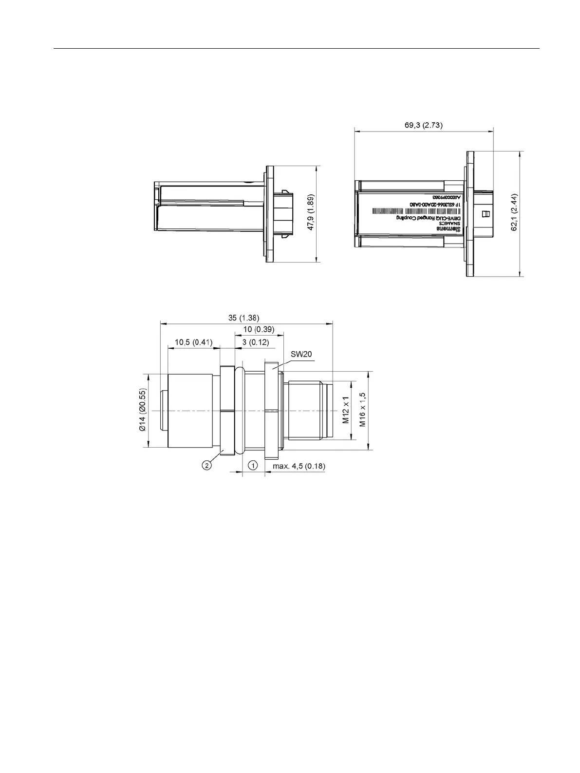
Figure 11-3 Dimension drawing of the DRIVE-CLiQ cabinet gland, all dimensions in mm and (inches)
Figure 11-4 Dimension drawing of the DRIVE-CLiQ cabinet bushing M12, all dimensions in mm and
(inches)

 Loading...


