Line-side power components
3.8 Line connection versions
SINAMICS S120 Combi
Manual, 11/2017, 6SL3097-4AV00-0BP7
53
For example S
K line
for 16 kW S120 Combi Power Module: S
K line
= 0.82 MVA = 820 kVA
From S
K transformer
the required rated power of the matching transformer can be calculated.
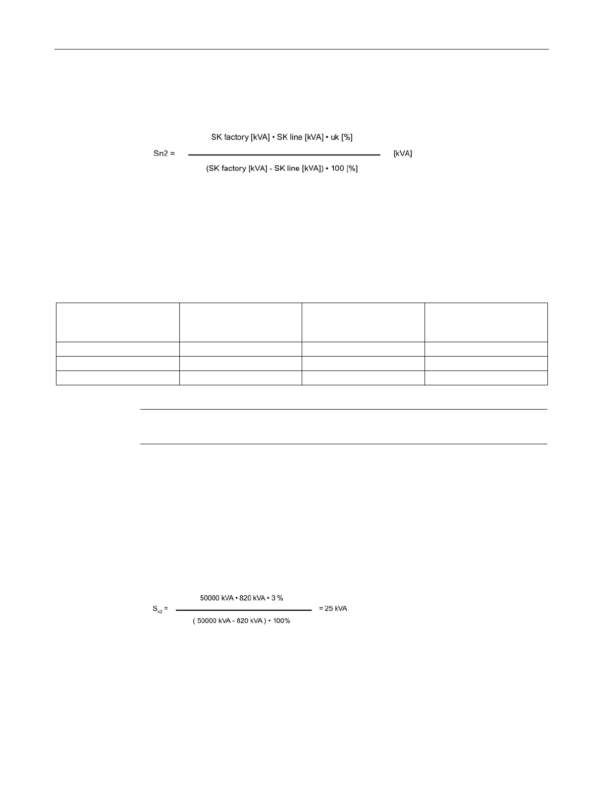
The short-circuit power at the factory connection S
K factory
plays a decisive role in
dimensioning the matching transformer.
From the rated power (S
n1
or S
n2
) calculated under a) and b), the higher value must be used
for the matching transformer.
Table 3- 6 Engineering notes for the transformer
S120 Combi Power Module
P
n
Required rated power S
n
of
the isolating transform-
er/autotransformer
Required short-circuit
voltage u
k
Required system fault level
S
K line
n
k
K line
Note
Ask your local power utility company for the system fault level S
K line
.
u
k
matching transformer = 3 %
S
K factory
= 50000 kVA
S
K line
= 16 kW • 70 • 0.73 = 820 kVA
according to a)
S
n1
= 1.27 • 16 kW = 21 kVA
According to b)
S
n2
> S
n1
⇒ S
n2
is decisive.
The matching transformer requires a rated power S
n
of 25 kVA for a short-circuit voltage u
k
of 3%.

 Loading...


