Cabinet design and EMC Booksize
12.4 Arrangement of components and equipment
Booksize Power Units
672 Manual, (GH2), 07/2016, 6SL3097-4AC00-0BP8
To calculate the load of the DC link busbar, add the DC link currents I
d
of the connected
Motor Modules. If the current carrying capacity of the DC link busbars is exceeded for the
planned configuration, two solutions are possible:
● Center infeed: Arrangement of the drive line-up with infeed to the left and right (example
2)
● Use of another Line Module
Note
The following examples are based on the simultaneous use and loading of the Motor
Modules with the rated current I
n
. The values of the DC link current were taken from the
technical data of the Motor Modules in the Power Units B
ooksize Manual.
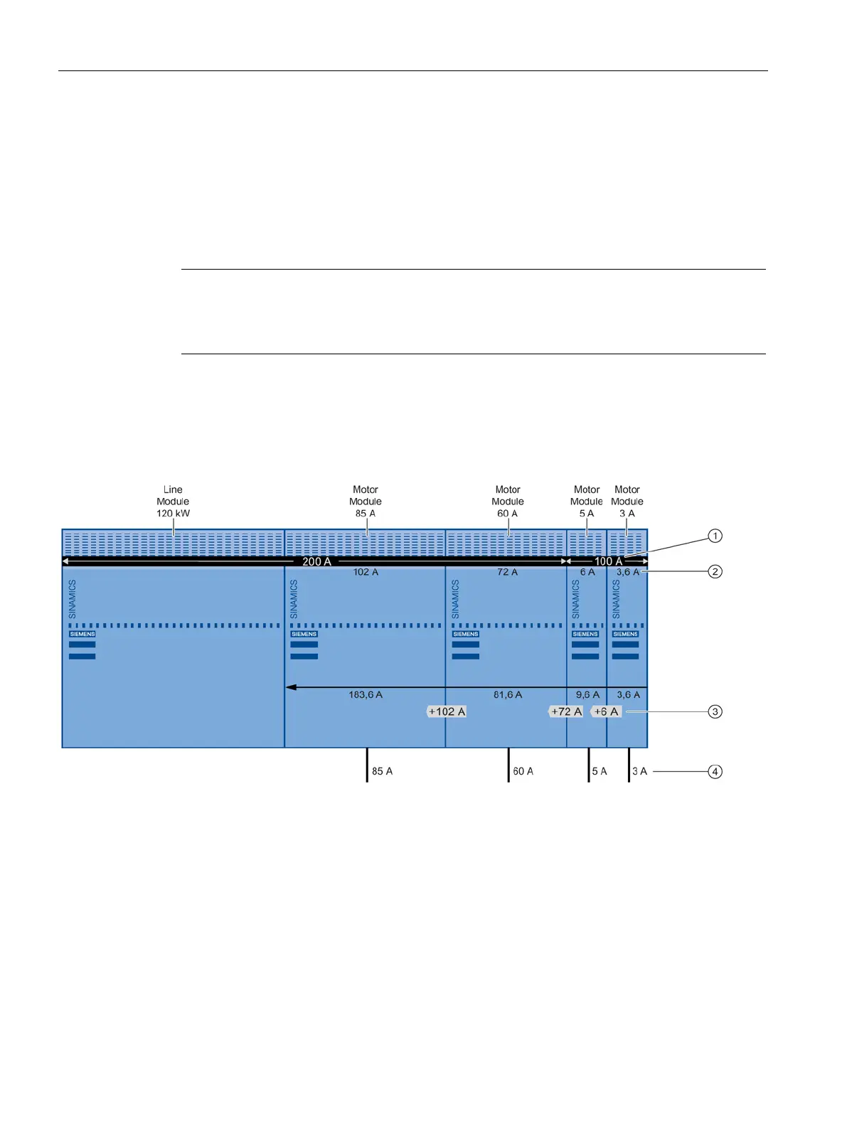
Connection of several Motor Modules with different current carrying capacity of the DC link
busbar to a Line Module.
DC link busbar current carrying capacity
DC link busbar load: DC link current I
d
at the rated current I
n
of the Motor Module
Increased load of the DC link busbar
Motor current = rated output current I
n
of the Motor Module
Figure 12-2 Regular arrangement with infeed to the right of the DC link, DC link busbar not overloaded

 Loading...


