Cabinet design and EMC Booksize
12.4 Arrangement of components and equipment
Booksize Power Units
Manual, (GH2), 07/2016, 6SL3097-4AC00-0BP8
673
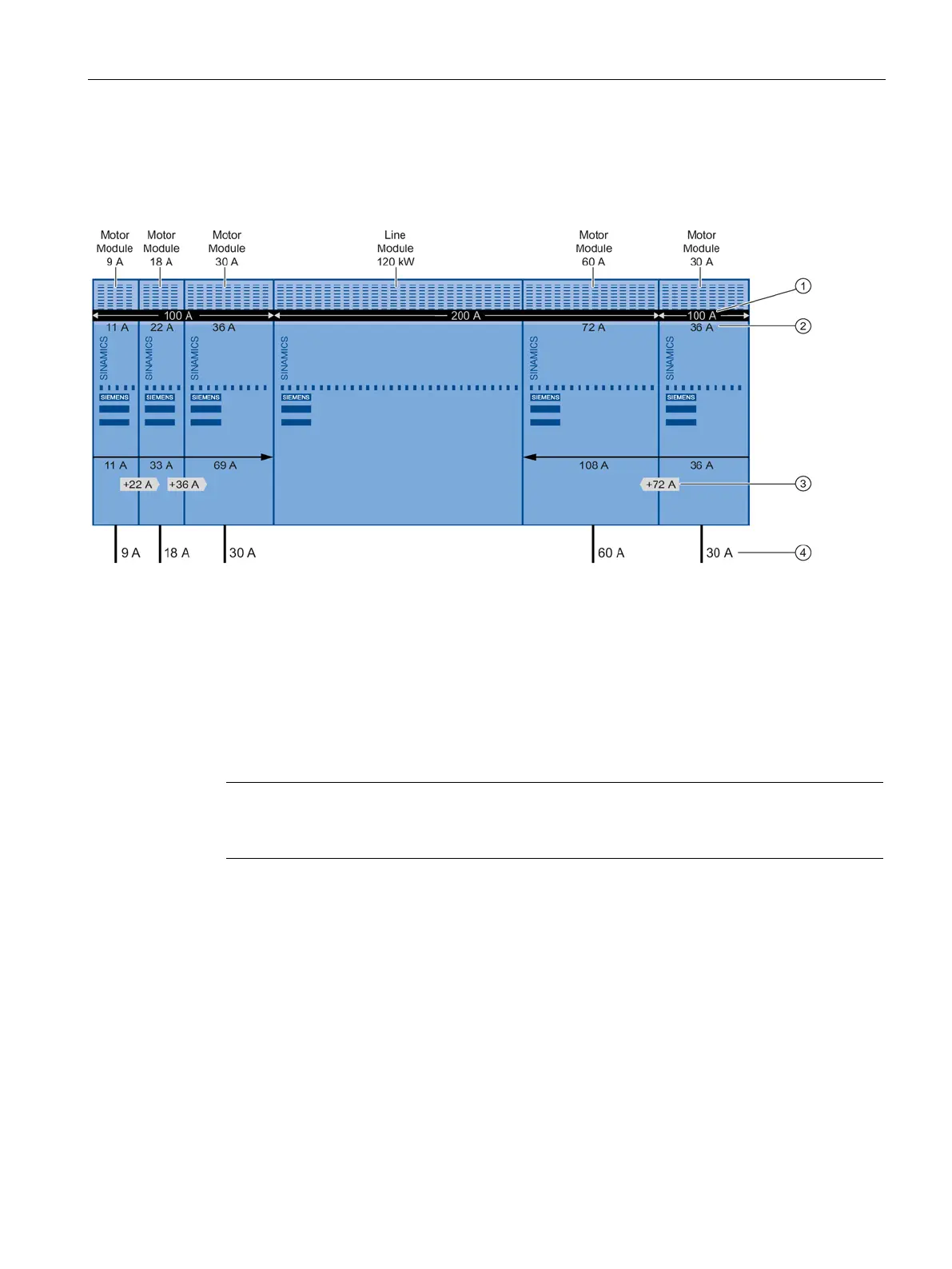
Connection of several Motor Modules with different current carrying capacity of the DC link
busbar to a Line Module with center infeed
DC link busbar current carrying capacity
DC link busbar load: DC link current I
d
at the rated current I
n
of the Motor Module
Increased load of the DC link busbar
Motor current = rated output current I
n
of the Motor Module
Figure 12-3 Center infeed - infeed from left and right to the DC link
A center infeed with Motor Modules to the right and left of the Line Module can be configured
for all Line Modules in compliance with current carrying capacity.
Exception: Smart Line Modules 5 kW and 10 kW
Note
For Smart Line Modules 5
kW and 10 kW, the arrangement of the drive line-up must be

 Loading...


