Procedure
Proceed as follows to attach an output element (for example, a coupling) to the motor:
1. Select a coupling.
Use a exible coupling with high torsional rigidity specically designed for servo motors,
which can transfer the motor torque to the mechanics and compensate radial, axial, and
angular misalignments.
2. Install the coupling.
Do not strike the shaft when installing a coupling. Ensure that the radial and axial forces are
smaller than the allowable maximum values specied in Section "Axial and radial forces
(Page635)".
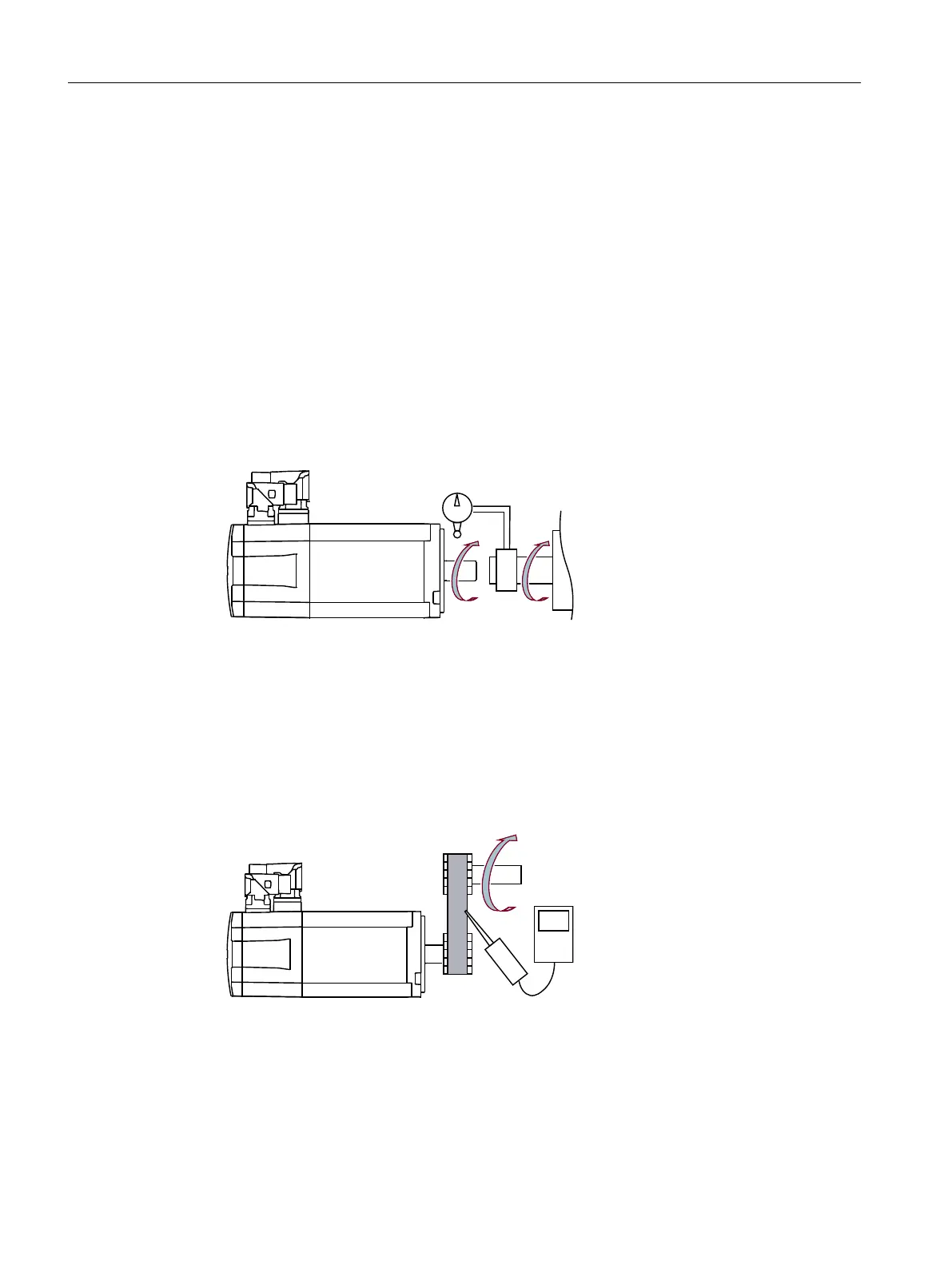
3. Align the coupling.
When a motor is used with a ange coupling, the radial deviation must be smaller than
0.03 mm; otherwise, the bearing will be damaged. The required alignment accuracy varies
with the motor speed and the coupling type. Determine the accuracy according to actual
applications.
– Rotate the motor shaft and the machine shaft to align the coupling.
– An
alignment
accur
acy test is preferred. If unachievable, judge the accuracy by observing
whether the coupling can slide smoothly on both shafts.
4. Realign the coupling.
If the coupling gives out abnormal sounds, refer to Step 3 "Align a coupling" to realign the
coupling until the sounds disappear.
5. Measure tension.
The belt tension must be smaller than the allowable radial forces of the motor.
– Measur
e the belt tension at multiple points using a tension meter while turning the motor
shaf
t b
y 45°.
– Reduce the axial misalignment of the belt-pulleys to keep the axial forces to the motor
shaft to a minimum.
Mounting
5.2Motor
SINAMICS S200 PROFINET servo drive system with SIMOTICS S-1FL2
122 Operating Instructions, 11/2023, FW V6.3, A5E51646752B AB