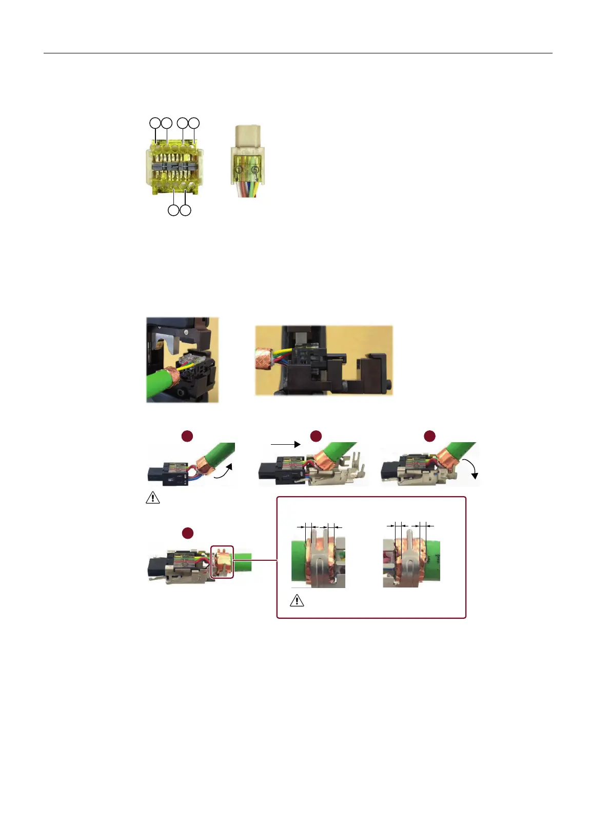
3. Insert the conductors into the connector with the correct order, pushing through until the
conductor ends reac
h the end of the connector.
Pin Conductor color Pin Conductor color
1 White 5 Yellow
2 Red 7 Pink
4 Green 8 Blue
4. Inser
t the connector into the IDC slot in the crimping tool and crimp the connector. Make sure
t
hat r
ed, yellow, and green conductors face up.
5. Assemble the shielding A.
DEF
G
DE
D
E
&OLFN
5LJKW
/HIW
0DNHVXUHWKDWUHG\HOORZ
DQGJUHHQFRQGXFWRUVIDFH
XS
5LJKW/HIW
0DNHVXUHWKDWD EDQGD E
Appendix
A.4Assembling cables
SINAMICS S200 PROFINET servo drive system with SIMOTICS S-1FL2
882 Operating Instructions, 11/2023, FW V6.3, A5E51646752B AB