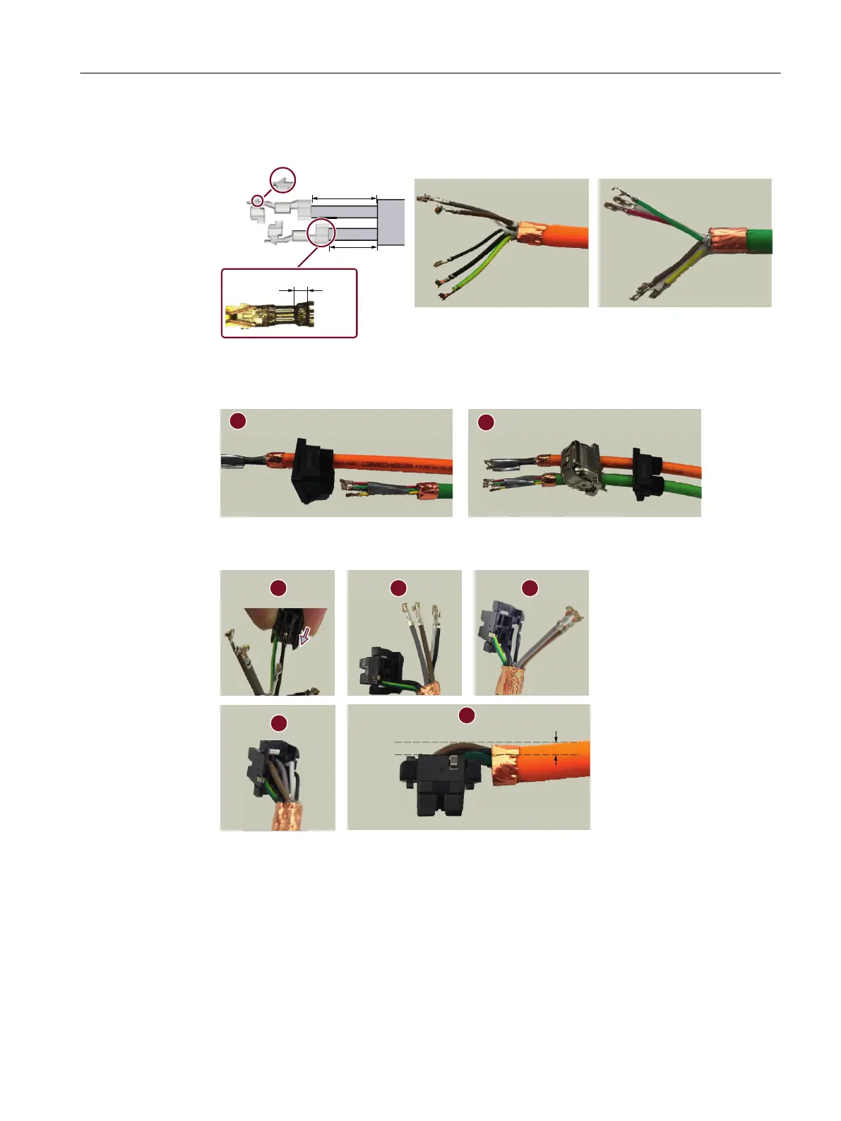
5. Crimp the contacts onto the conductors. Make sure that the lance side of the contacts face
outwar
ds.
/DQFH
PPPP
PPPP
PPPP
6. Slide the power and signal cables through the seal case and the housing.
Avoid def
orming the contact tips. Siemens recommends that you protect the conductors
with a tape during the process.
7. Insert the power and brake contacts into the power unit case and adjust the conductors to
make sure t
hat the cable does not rise up.
Appendix
A.4Assembling cables
SINAMICS S200 PROFINET servo drive system with SIMOTICS S-1FL2
Operating Instructions, 11/2023, FW V6.3, A5E51646752B AB 889