Section 04 TRANSMISSION
Sub-Section 02 (DRIVE BELT)
04-02-2
DRIVE BELT DEFLECTION
MEASUREMENT 2
NOTE :
The drive belt deflection measure-
ment must be performed each time a new
drive belt is installed.
NOTE :
To obtain an accurate drive belt de-
flection measurement, it is suggested to al-
low a break-in period of 50 km (30 mi).
Before checking the belt deflection, ensure vehi-
cle has the proper belt (Refer to the application
chart).
Adjust pulley distance and alignment. Refer to 04-
05 PULLEY DISTANCE AND ALIGNMENT.
To obtain maximum vehicle performance, the belt
tension must be adjusted according to specifica-
tions shown in the accompanying chart.
†
For reference only
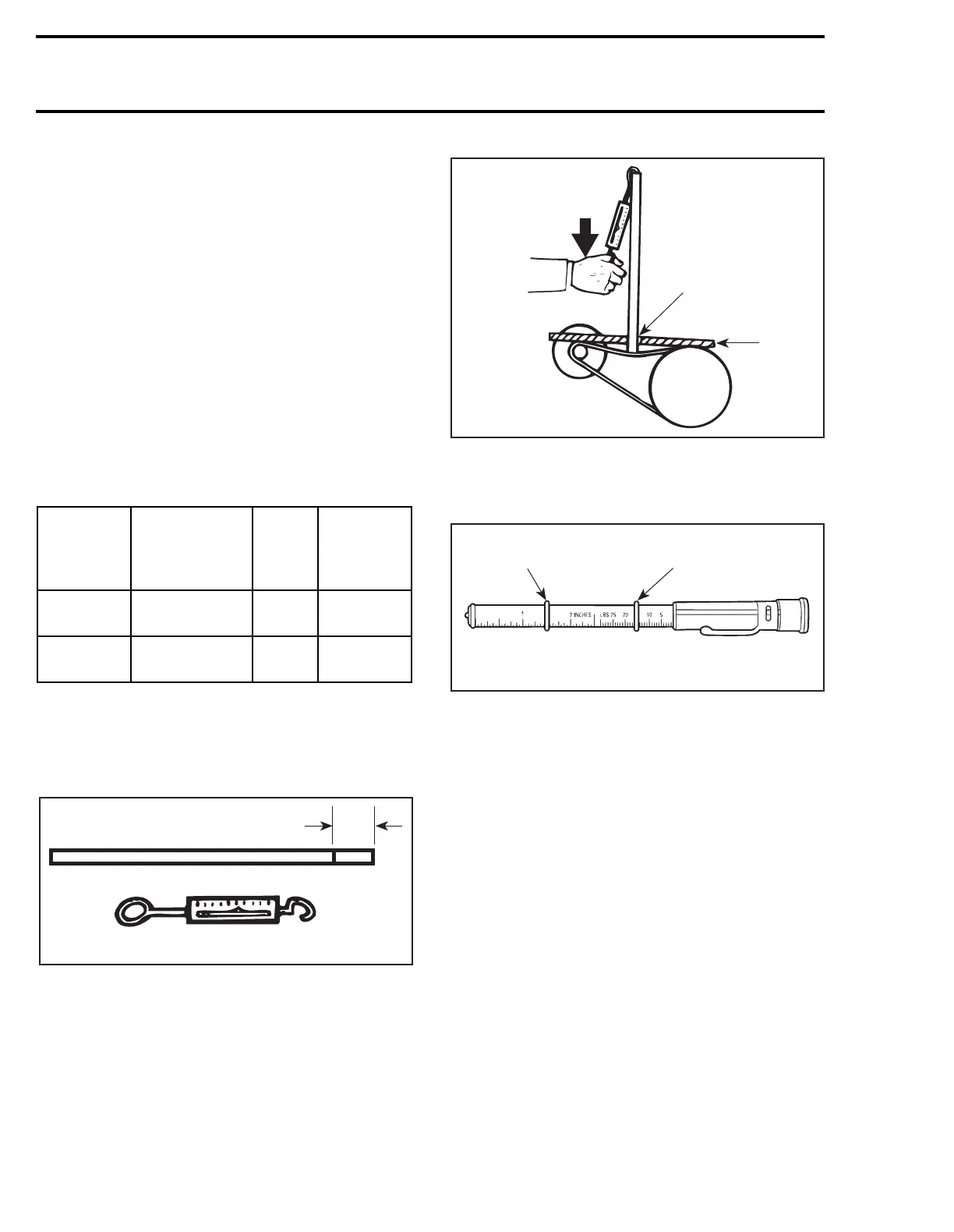
To Check Tensi on
Position a reference rule on drive belt.
Wooden Stick and Spring Scale Method :
1. Mark specified deflection
Using spring scale and stick, apply specified force
on drive belt halfway between pulleys as shown.
1. Read deflection here
2. Reference rule
3. Force
Or use the belt tension tester (P / N 414 3482 00).
1. Lower O-ring
2. Upper O-ring
3. Force (Read Down)
4. Deflection (Read Up)
1. Slide lower O-ring of deflection scale to speci-
fied measure.
2. Slide upper O-ring to zero on the force scale.
3. Apply pressure until lower O-ring is flush with
edge of rule and read force on the upper scale
at top edge of O-ring.
MODEL
DEFLECTION
mm (in)
FORCE
kg (lb)
HEIGHT
†
OVER
DRIVEN
PULLEY
Tundra II LT
32
±
5
(1-1/4
±
13/64)
5(11)
0 - 1.5 mm
(0 - 1/16’’)
S-Series
32
±
5
(1-1/4
±
13/64)
11.3
(25)
0 - 1.5 mm
(0 - 1/16’’)
'
A00D05A
1
A00D06A
1
2
3
12
34
{
{
A00C07B