Section 05 ELECTRICAL
Sub-Section 05 (TESTING PROCEDURE)
05-05-7
RESISTANCE MEASUREMENTS
As an alternate method, magneto system compo-
nents can be checked with a digital ohmmeter.
NOTE:
All resistance measurements must be
performed with parts at room temperature (borax.
20°C (68°F)). Temperature greatly affects resis-
tance measurements.
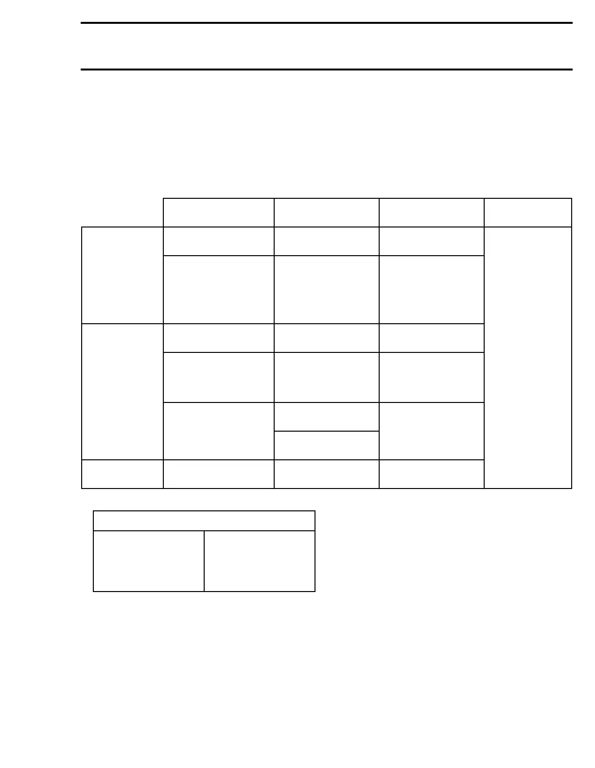
Disconnect connector at ignition coil and magneto
junction. Measure resistance between each ter-
minal. Refer to the following table for values and
wire colors.
NOTE:
An ignition coil with good resistance mea-
surement can still be faulty. Voltage leak can occur
at high voltage level which is not detectable with
an ohmmeter.
∞: Infinity (extremely large number)
PART
NAME
WIRE COLOR*
RESISTANCE
OHM
REMARKS
MAGNETO Trigger
coil
BL/YL
with WH/YL
190 - 300
No display change
means open
circuit.
Ignition
generator
coil
Low
speed WH with RD 49 - 75
High
speed
WH
with BK / RD
2.8 - 4.3
IGNITION
COIL
Primary
winding
BK with WH/BL 0.3 - 0.7
Secondary
winding
(spark plug
cap remove)
End of each high
tension wire
8 - 16 K
(8000 - 16000)
Display showing
zero (0) means
short circuit.
Insulation WH/BL
with core
∞Ω
WH/BL with high
tension wire
SPARK PLUG
CAP
Spark plug
cap
— 4.5 - 5.5 K
*
COLOR CODE
BK — BLACK
WH — WHITE
RD — RED
BL — BLUE
YL — YELLOW
GN — GREEN
GY — GREY
VI — VIOLET
OR — ORANGE
BR — BROWN