03-3
Section 03 ELECTRICAL SYSTEM
Connect an ohmmeter probe to ground and the
other probe to each of the yellow wires.
There must be no continuity.
1. 2-01 housing disconnected
2. Ohmmeter probes
Voltage Regulator
The battery must be at room temperature. Con-
nect a DC voltmeter to the battery. Note voltage.
If the battery is charged, the voltmeter shall indi-
cate 12.5 ± 0.3 VDC.
Start the engine. The voltage must increase de-
pending on engine speed.
HEATING ELEMENTS
SWITCHES SYSTEM
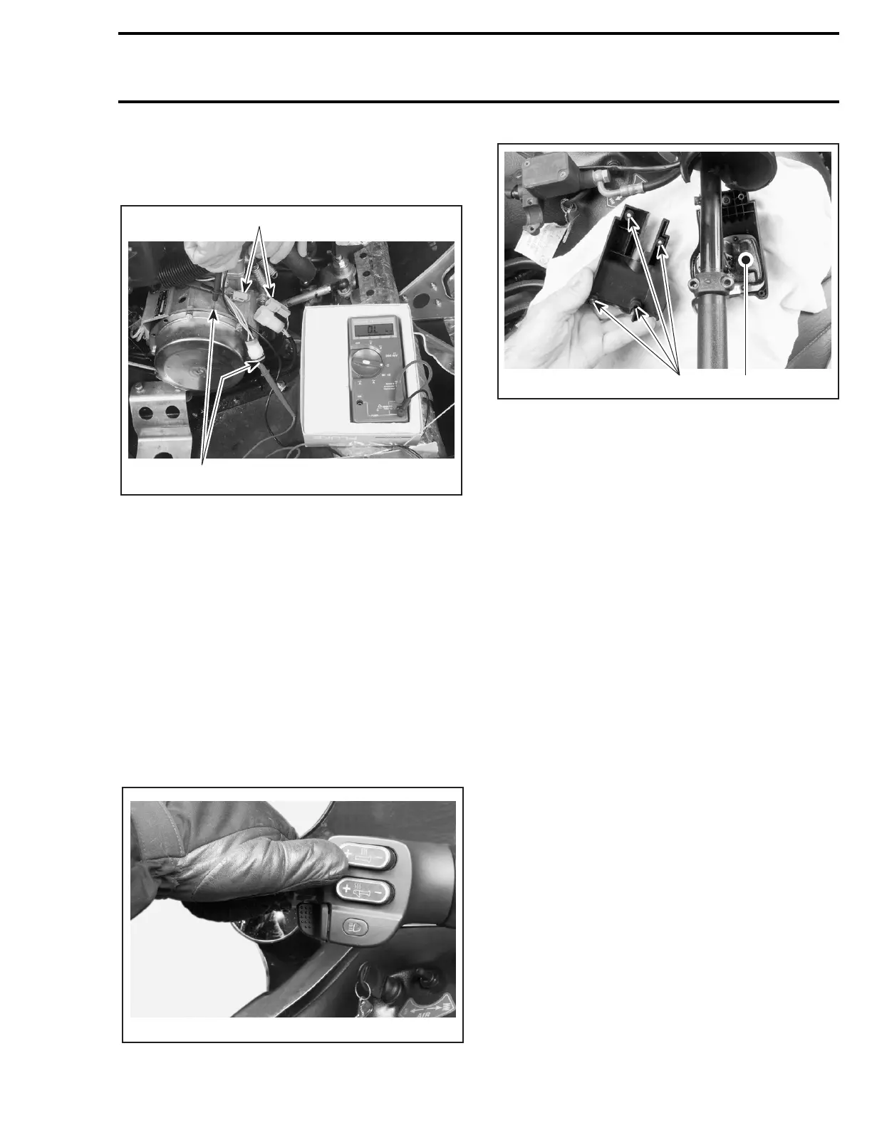
COMPONENT LOCATION
1. Intensity control module
2. Screw location
THEORY AND OPERATION
Heating Elements Switches
These toggle switches allow selecting 5 different
heating levels from the heating elements (heated
grips and heated throttle).
Each time the engine is started, the lowest heat-
ing intensity is selected.
Press switch at the desired position. Clicking + to
increases heating and clicking - decreases it.
When holding switch for more than about 1 sec-
ond will increase to maximum intensity or OFF po-
sition according selected position.
Intensity Control Module
This module controls the current returning from
heating elements. This module also controls the
dimmer switch.
TESTING PROCEDURE
Intensity Control Module
If indicator lights are on, the module works. This
module cannot be repaired. It must be replaced
when defective.
Removal
Remove brake master cylinder. See previous pho-
to.
Unscrew the 4 screws holding the module to the
handlebar.
A06E2SA
2
1
A06H2UB
A06E2UA
12