Section 04 TRANSMISSION
Sub-Section 06 (BRAKE)
04-06-6
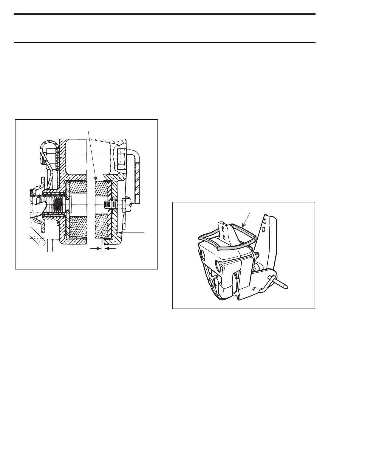
INSPECTION
7, Brake Pad Thickness
Brake pads must be replaced when
fixed
pad
projects only 1 mm (1/32 in) from caliper.
CAUTION : Brake pads must always be re-
placed in pairs.
TYPICAL
1. Fixed pad
2. Inner caliper
A. 1 mm (1/32 in) minimum
Brake Disc
Check for scoring, cracking or heat discoloration,
replace as required. Refer to DRIVEN PULLEY 04-
04 for replacement procedures on Tundra II LT.
CAUTION : Brake disc should never be
machined.
ASSEMBLY
14, Ratchet Wheel
Apply low temperature grease (P / N 413 7061 00)
on threads and spring seat prior to installing. Fully
tighten then back off one turn.
16, Pin
Install so that it can only be removed upward.
Lock it in the caliper casting notch.
7, Fixed Brake Pad
Tundra II LT
Torque screw
no. 3
to 4 N•m (35 lbf•
in
). Bend
locking tab
no. 4
over a flat of screw head.
1,6,11,12, Locking Tab, Inner, Outer
Caliper and Nut
Tundra II LT
Assemble both caliper halves. Insert bolts
no. 9
,
locking tab
no. 20
, then nuts. Torque nuts to 24
N•m (18 lbf•ft). Caliper half side slots must align
to allow proper sliding in brake support. Bend
locking tab over a flat of each nut.
Install rubber slider
no. 12
lubricated with short-
ening (cooking fat) into side slots of caliper. It
must be installed so that the raised edge is up-
ward and on the same side of nuts as shown.
1. Raised edge upward and same side of nuts
CAUTION : Positioning of rubber slider is
important to avoid the possibility of dam-
age against locking tab edges.
INSTALLATION
To install brake, reverse removal procedure paying
attention to the following.
WARNING : Avoid getting oil on brake
pads. Do not lubricate or apply antirust or
antifreeze solution in brake cable.
17, Brake Disc
S-Series
The brake disc must be floating on countershaft
for efficient operation of brake.
A15D03A
A
2
1
A20D04A
1
;