Section 04 TRANSMISSION
Sub-Section 03 (DRIVE PULLEY)
04-03-2
GENERAL
Some drive pulley components (return spring, cal-
ibration disk) can be changed to improve vehicle
performance in high altitude regions. The High Al-
titude Technical Data booklet (P / N 484 0648 00
and 484 0545 00 for binder) gives information
about calibration according to altitude.
CAUTION : Such modifications should
only be performed by experience me-
chanics since they can greatly affect vehicle
performance.
WARNING : Any drive pulley repairs
must be performed by an authorized
Bombardier snowmobile dealer, or other such
qualified person. Sub-component installation
and assembly tolerances require strict adher-
ence to procedures detailed.
REMOVAL
NOTE :
If disassembling drive pulley, first
straighten tab washer
no. 7
then untighten
nut
no. 8
.
Use clutch holder (P / N 529 0276 00).
TYPICAL
Remove retaining screw
no. 9
.
Insert drive pulley puller (P / N 529 0314 00) then
remove drive pulley.
TYPICAL
DISASSEMBLY
Unscrew nut. Remove tab washer.
Mark governor cup
no. 6
and sliding half
no. 3
for
proper indexing at reassembly.
Identify blocks
no. 1
and their respective positive
positions for reassembly.
1. Identify
2, Nylon Threaded Plug
These are calibration parts. Refer to TECHNICAL
DATA 09-03.
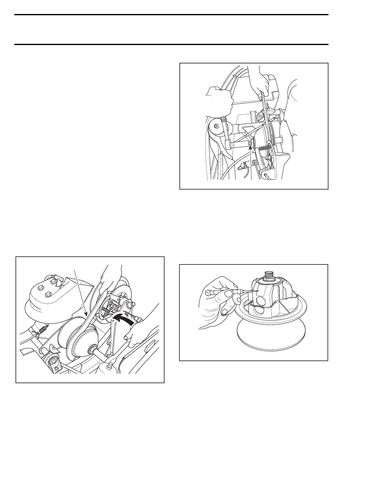
Unscrew set screw
no. 4
then use spring cover
tool (P / N 529 0273 00) to unscrew spring cover
no. 5
.
Mount tool in a vise for cover hand-unscrewing.
;
A05D0JB
529 0276 00
A05D0KA
529 0314 00
A05D0LA
1
1