Section 03 ENGINE
Sub-Section 02 (277 ENGINE TYPE)
03-02-4
TROUBLESHOOTING
Before completely disassemble engine, check air-
tightness. Refer to LEAK TEST AND ENGINE DI-
MENSION MEASUREMENT 03-04.
NOTE :
The following procedures can be
done without removing the engine from
chassis.
TOP END REMOVAL (without
removing engine from chassis)
Remove the following then lift cylinder head
no. 3
and cylinder
no. 4
:
– belt guard
– carburetor
– exhaust system
– spark plug
– oil injection inlet
– fan cowl and hood cable
– cylinder head nuts
no. 1
and washers
no. 2
CLEANING
Discard all gaskets.
Clean all metal components in a non-ferrous met-
al cleaner.
Scrape off carbon formation from cylinder ex-
haust port, cylinder head and piston dome using a
wooden spatula.
NOTE :
The letters “AUS” (over an arrow on
the piston dome) must be visible after clean-
ing.
Clean the piston ring grooves with a groove clean-
er tool, or with a piece of broken ring.
DISASSEMBLY
5, Piston
On this engine, piston pin needle bearing
no. 6
is
mounted without a cage.
Use piston pin puller (P / N 529 0210 00) along
with expansion sleeve and locating sleeve.
Place a clean cloth or rubber pad (P / N 529 0234
00) over crankcase to prevent circlips
no. 8
from
falling into crankcase. Then with a pointed tool in-
serted in piston notch, remove circlips from pis-
ton
no. 5
.
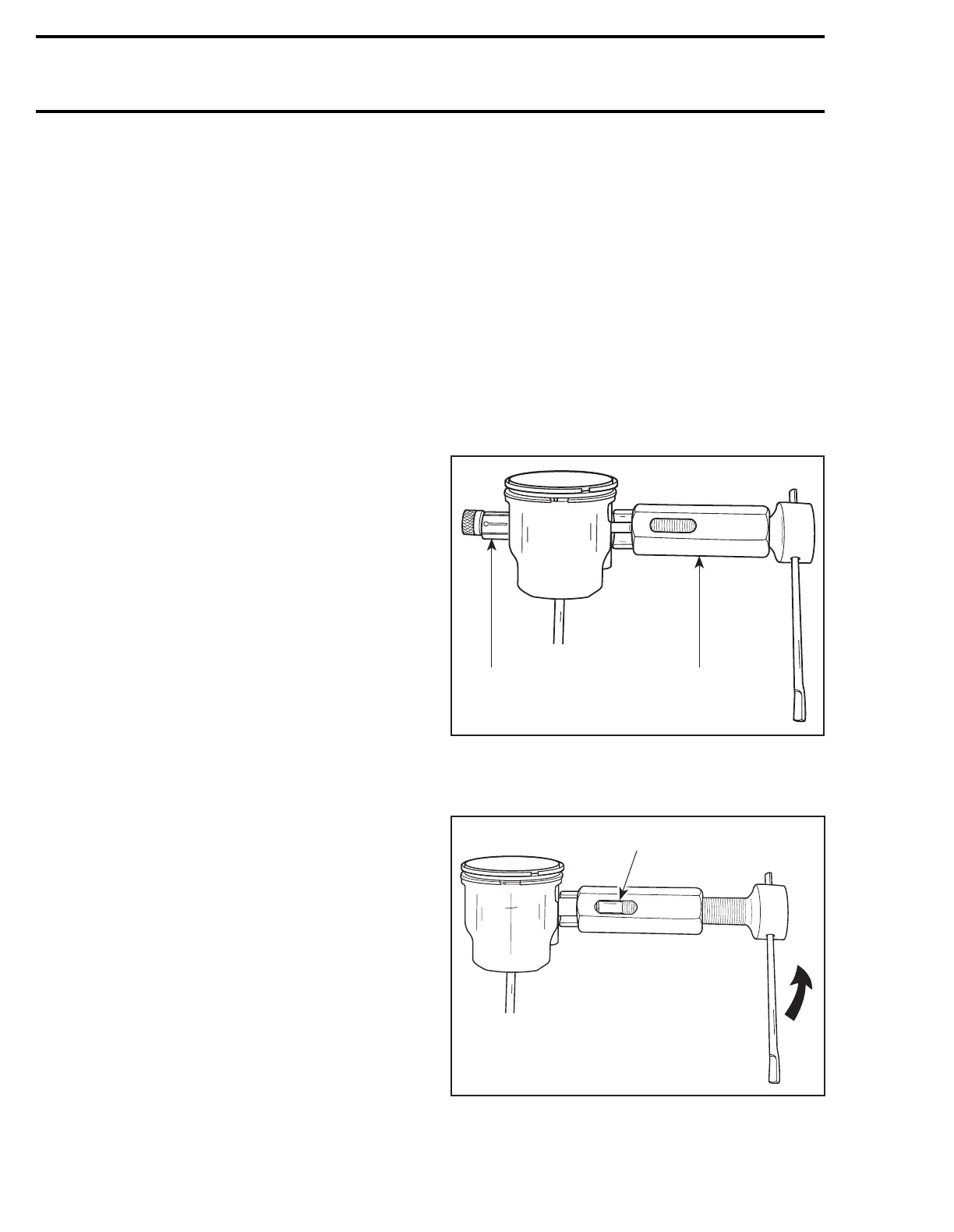
Insert piston pin puller (P / N 529 0210 00) then
install expansion sleeve over puller rod.
1. Expansion sleeve
Pull out piston pin
no. 7
by unscrewing puller until
first thread of puller rod aligns with 277 mark.
1. 277 mark on puller
Screw in puller in order to remove it from piston.
'
A21C06A
1
529 0210 00
A21C05A
1