Section 04 TRANSMISSION
Sub-Section 03 (DRIVE PULLEY)
04-03-12
Raise and block the rear of the vehicle and sup-
port it with a mechanical stand.
WARNING : Ensure that the track is free of
particles which could be thrown out while
track is rotating. Keep hands, tools, feet and
clothing clear of track. Ensure nobody is stand-
ing near the vehicle.
Accelerate the vehicle at low speed (maximum 30
km / h (20 MPH) and apply the brake, repeat 5
times.
Recheck the torque of 90 to 100 N•m (66 to 74
lbf•ft).
WARNING : After 10 hours of operation
the transmission system of the vehicle
must be inspected to ensure the retaining
screw is properly torqued.
DRIVE PULLEY ADJUSTMENT
The drive pulley is factory calibrated to transmit
maximum engine power at a predefined RPM.
Factors such as ambient temperature, altitude or
surface condition may vary this critical engine
RPM thus affecting snowmobile efficiency.
This adjustable drive pulley allows setting maxi-
mum engine RPM in the vehicle to maintain max-
imum power.
Calibration screws should be adjusted so that ac-
tual maximum engine RPM in vehicle matches
with the maximum horsepower RPM given in
TECHNICAL DATA 09.
NOTE :
Use precision digital tachometer for
engine RPM adjustment.
NOTE :
The adjustment has an effect on
high RPM only.
To adjust, modify ramp end position by turning cal-
ibration screws.
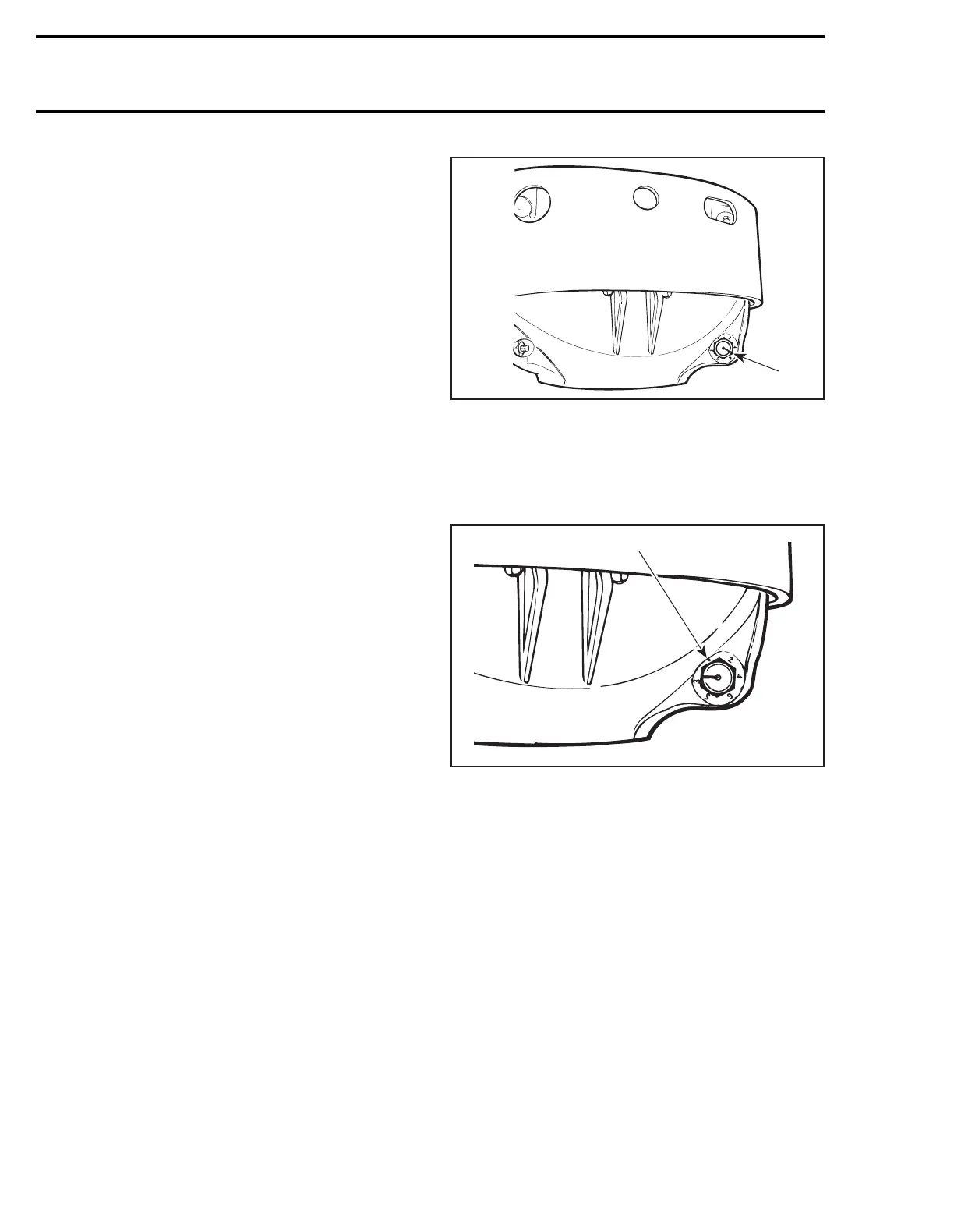
26,28,29, Calibration Screw, Locking
Nut and Governor Cup
Calibration screw has a notch on top of its head.
1. Notch
Governor cup has 6 positions numbered 2 to 6.
Note that in position 1 the number is substituted
by a dot (due to its location on casting).
See TECHNICAL DATA 09-03 for original setting.
1. Position 1 (not numbered)
Each number modifies maximum engine RPM by
about 200 RPM.
Lower numbers decrease engine RPM in steps of
200 RPM and higher numbers increase it in steps
of 200 RPM.
Example :
Calibration screw is set at position 4 and is
changed to position 6. So maximum engine RPM
is increased of 400 RPM.
To Adjust :
Just loosen locking nut enough to pull calibration
screw
partially
out and adjust to desired position.
Do not completely remove the locking nut. Torque
locking nuts to 10 N•m (89 lbf•
in
).
CAUTION : Do not completely remove
calibration screw or its inside washer will
fall off.
;
;
A16D0FA
1
A16D0GA
1