Section 03 ENGINE
Sub-Section 05 (CDI SYSTEM)
03-05-6
NOTE :
The following procedures can be
done without removing the engine from
chassis.
CLEANING
Clean all metal components in a non-ferrous met-
al cleaner.
CAUTION : Clean armature and magneto
using only a clean cloth.
DISASSEMBLY
To gain access to magneto assembly, remove the
following parts as needed on different engines :
– tuned pipe and muffler
– oil injection pump mounting plate from rewind
starter
– rewind starter
– starting and V-belt pulleys
NOTE :
Before disassembling armature
plate, indexing marks should be scribed to
facilitate reassembly.
To remove magneto flywheel retaining nut
no. 3
,
install puller ring (P/N 420 8760 80) and M8 x 20
screws.
– Remove magneto flywheel nut, using a 30 mm
socket machined to 40 mm (1.580 in) outside
diameter by 16 mm (5/8 in) long.
NOTE :
To correctly remove a threadlocked
fastener it is first necessary to tap on the fas-
tener to break threadlocker bond. This will elimi-
nate the possibility of thread breakage.
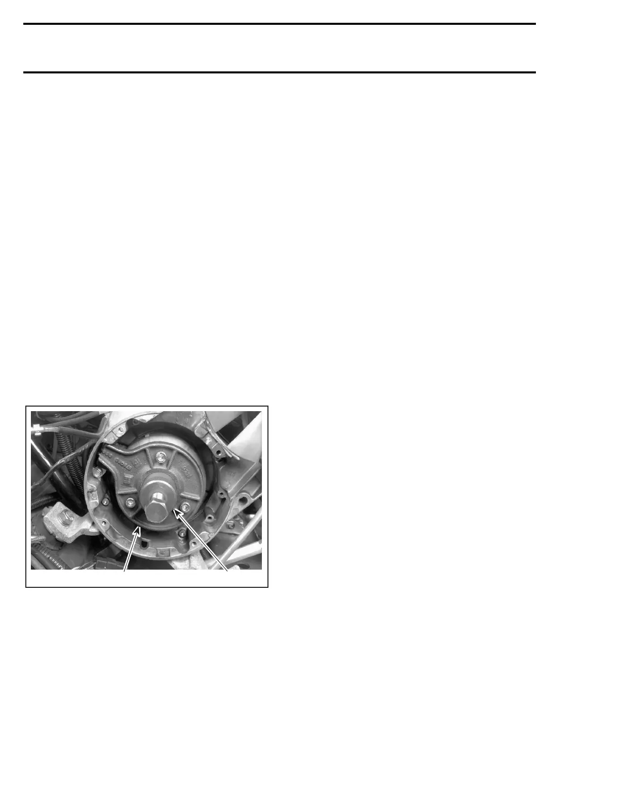
To remove magneto flywheel
no. 2
, install the
magneto puller (P/N 529 0225 00).
– Tighten puller bolt and at the same time, tap on
bolt head using a hammer to release magneto
flywheel from its taper.
REPAIR
To replace generator coil
no. 1
:
– Heat the armature plate to 93°C (200°F) around
the screw holes to break the threadlocker
bond.
To replace trigger coil
no. 4
:
– Disconnect trigger coil wire (RED).
– Remove grommet from crankcase where trig-
ger coil wire exits magneto housing.
– Remove retaining screws
no. 9
.
– Remove trigger coil and carefully pull wire.
– Install new trigger coil and other parts re-
moved.
Adjustment
Whenever the trigger coil or the magneto fly-
wheel is removed or replaced, the air-gap be-
tween the trigger coil and the flywheel protrusion
must be checked and adjusted. The purpose of
this adjustment is to obtain the minimum clear-
ance between these parts – without touching at
any RPM – so that the trigger coil produces its
proper electrical output. Ignition timing must also
be checked.
Proceed as follows :
1. Rotate flywheel so that one protrusion aligns
with trigger coil.
2. Using a feeler gauge of 0.45 mm (.018 in) to
0.55 mm (.022 in) thick, check air-gap between
center pole of trigger coil and flywheel protru-
sion.
3. If necessary, adjust by slackening retaining
screws and moving trigger coil toward or away
of protrusion.
4. Retighten screws and recheck air-gap.
A03C07A
529 0225 00420 8760 80