Section 04 TRANSMISSION
Sub-Section 03 (DRIVE PULLEY)
04-03-3
To Remove Drive Pulley Ass’y:
Retain drive pulley with clutch holder.
Install puller in pulley shaft then tighten.
DISASSEMBLY
1,2, Screw and Ring Gear
5,6, Fixed and Sliding Half
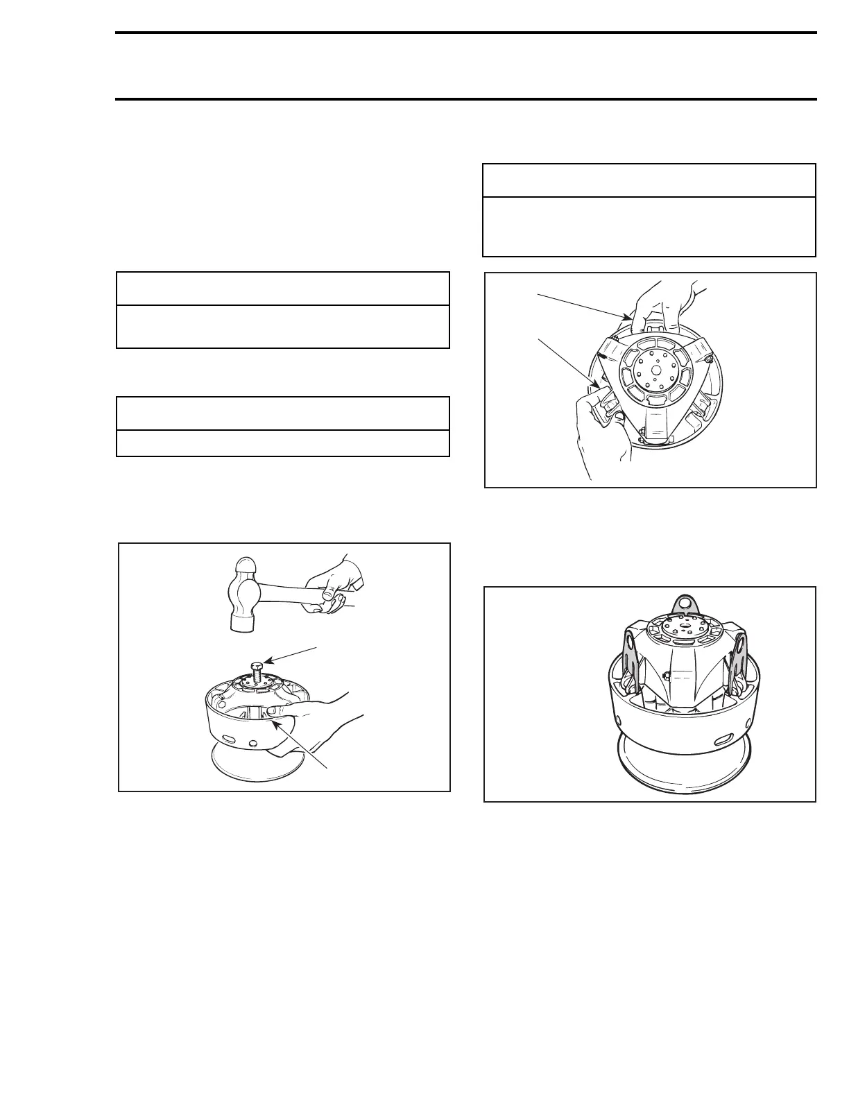
Screw puller into fixed half shaft about 13 mm (1/2
in). Raise drive pulley and hold it by the sliding half
while knocking on puller head to disengage fixed
half.
1. Puller
2. Holding sliding half
NOTE:
No components marking is required be-
fore disassembling this drive pulley since it has
factory mark and arrows as indexing reference.
25,29, Slider Shoe and Governor Cup
Carefully lift governor cup until slider shoes come
at their highest position into guides.
Hold a slider shoe set then carefully lift its housing
and remove them. Proceed the same way for other
housings lifting one at a time.
32, Cushion Drive
1. Hold slider shoes
2. Lift one housing at a time
NOTE:
To ease disassembly, forks (P/N 529 0055
00) should be used to hold slider shoes prior to
removing governor cup.
-
CAUTION
Retaining screws must be heated before dis-
assembly.
-
CAUTION
Do not tap on governor cup.
A16D01A
1
2
-
CAUTION
Do not disassemble cushion drive. Governor
cup and cushion drive are factory balanced
as an assembly.
A16D02A
1
2
A16B02A
529 0055 00