Section 05 ELECTRICAL
Sub-Section 07 (TESTING PROCEDURE)
05-07-2
➁
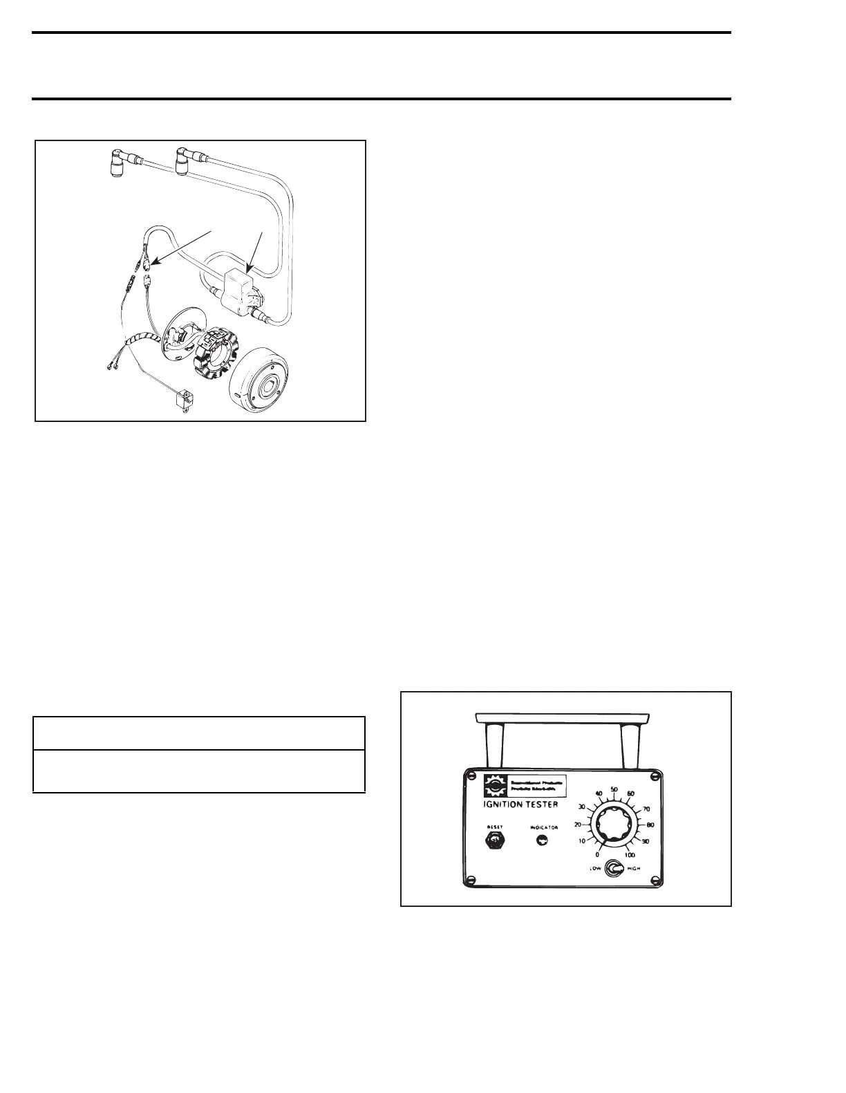
DUCATI CDI SYSTEM
1. Combined ignition module/ignition coil mounted on air silencer
below carburetor
2. Two-wire connector (GREEN/WHITE wires)
Ignition System Testing Sequence
When dealing with ignition problems, the follow-
ing items should be verified in this order.
Nippondenso
1. Spark occurrence/spark plug condition.
2. Electrical connections.
3. Engine stop/tether cord switches.
4. Ignition coil output.
5. Ignition module output.
6. Magneto output (ignition generator coil).
Ducati
1. Spark occurence/spark plug condition.
2. Electrical connections.
3. Engine stop/tether crod switches.
4. Trigger coil output.
5. Magneto output (ignition generator coil).
6. Ignition coil output.
7. Ignition module.
All Systems
The first 2 items can be checked with known au-
tomotive equipment and other items as follows.
Engine Stop/Tether Cut-Out Switches
Verification
Engine Stop Switch
Unplug stop switch connector from main harness
then using an ohmmeter, connect test probes to
BLACK/YELLOW and BLACK wires.
Measure resistance, it must be an open circuit in
its operating position and close to 0 ohm when
depressed.
Tether Cut-Out Switch
Unplug tether cut-out switch connector from
main harness then using an ohmmeter, connect
test probes to BLACK/YELLOW and BLACK
wires.
Measure resistance, it must be an open circuit
when cap is over switch and close to 0 ohm when
removed.
Magneto System Verification
System verification can be performed using the
Bombardier ignition tester (P/N 419 0033 00), a
digital ohmmeter or by substituting parts.
USE OF BOMBARDIER IGNITION
TESTER
NOTE:
For more information about operat-
ing and maintenance of the tester, refer to its
instruction manual.
-
CAUTION
Whenever replacing a component in ignition
system, check ignition timing.
A17E0TA
1
2
A00E0EA
'