Section 05 ELECTRICAL
Sub-Section 02 (WIRING DIAGRAMS)
05-02-3
Connector Location
Connectors on wiring diagrams carry the letter C
followed by a number. Use this code with wiring
diagram legend to find connector location on vehi-
cle.
UNPLUGING CONNECTORS
Always unplug connectors by pulling on housing
not on wire.
TYPICAL
TAB AND RECEPTACLE
CONNECTORS REMOVAL
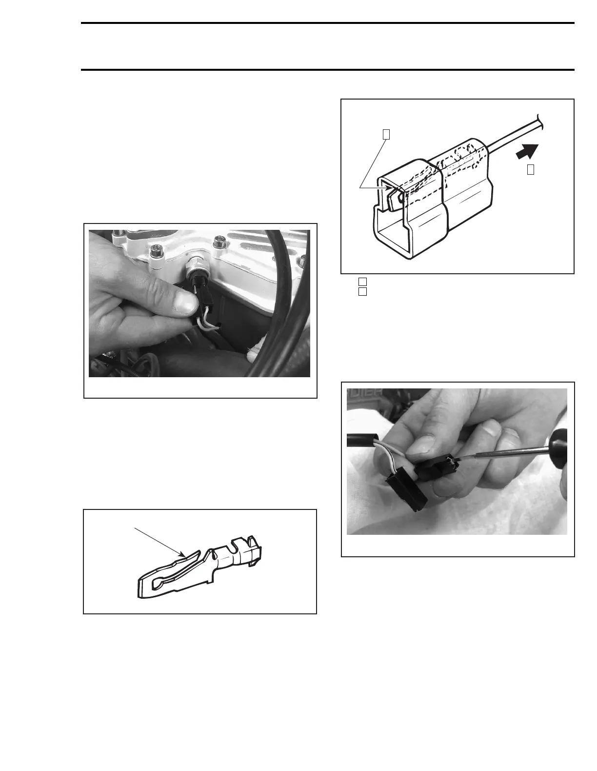
Tab Connector
It is locked in its housing by a spring tab on its
side. Removal is done by squeezing this tab.
TAB CONNECTOR
1. Locking tab
To remove:
– Insert a screwdriver or Snap-on TT 600-5 from
opposite side of wire and pry locking tab.
– While holding locking tab pried, pull connector
toward wire side.
Step : Insert screwdriver here
Step : Pull this side
Locking Receptacle Connector
To remove:
– Insert tool Snap-on TT 600-5 in access opening
then pull housing toward wire side.
TAB AND RECEPTACLE
CONNECTORS INSTALLATION
Prior to installing, make sure locking tab is suffi-
ciently lifted to properly lock.
Insert tab and receptacle connectors in their re-
spective housings as shown in following illustra-
tions. Push sufficiently so that they snap. Try
pulling wire to ensure they are properly locked.
A06E1PA
A00E1DA
1
A00E1EA
2
1
1
2
A06E1QA