Section 04 TRANSMISSION
Sub-Section 03 (DRIVE PULLEY)
04-03-5
GENERAL
Some drive pulley components (return spring,
ramp) can be changed to improve vehicle perfor-
mance in high altitude regions. The High Altitude
Technical Data booklet (P / N 484 0624 00 and 484
0545 00 for binder) gives information about cali-
bration according to altitude.
CAUTION : Such modifications should
only be performed by experienced me-
chanics since they can greatly affect vehicle
performance. Verify spring specifications be-
fore installation. Do not only refer to the spring
color code.
NOTE :
TRA clutch stands for Total Range
Adjustable clutch.
WARNING : Any drive pulley repairs must
be performed by an authorized Bombar-
dier snowmobile dealer, or other such quali-
fied person. Sub-component installation and
assembly tolerances require strict adherence
to procedures detailed.
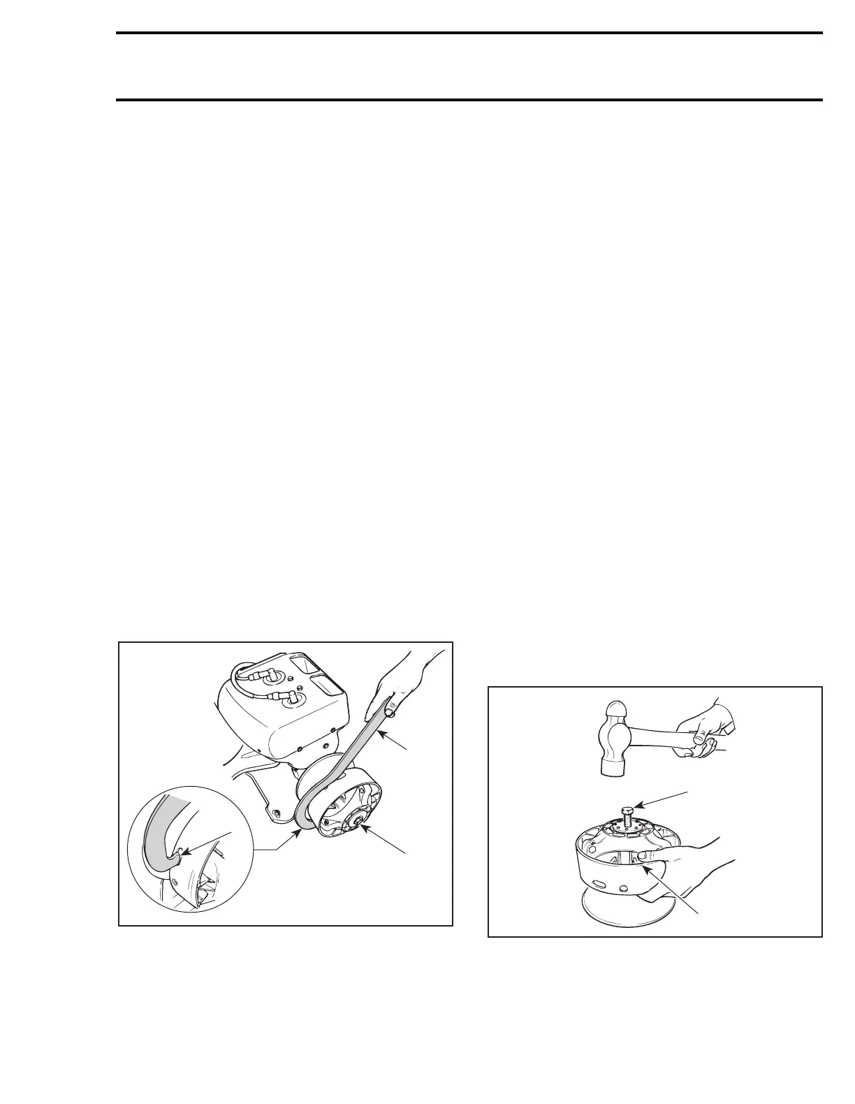
REMOVAL
30,31, Conical Spring Washer and
Screw
Use clutch holder (P / N 529 0064 00).
TYPICAL
1. Retaining screw
2. Insert in any slot
NOTE :
Sliding half can be removed while
fixed half remains on crankshaft.
WARNING : Never use any type of impact
wrench at drive pulley removal and instal-
lation.
Remove retaining screw.
To remove drive pulley ass’y and / or fixed half
from engine, use puller (P / N 529 0079 00).
CAUTION : These pulleys have metric
threads. Do not use imperial threads pull-
er. Always tighten puller by hand to ensure
that the drive pulley have the same type of
threads (metric vs imperial) prior to fully tight-
en.
To Remove Drive Pulley Ass’y :
Retain drive pulley with clutch holder.
Install puller in pulley shaft then tighten.
DISASSEMBLY
1,2, Screw and Ring Gear
CAUTION : Retaining screws must be
heated before disassembly.
5,6, Fixed and Sliding Half
CAUTION : Do not tap on governor cup.
Screw puller into fixed half shaft about 13 mm (1/2
in). Raise drive pulley and hold it by the sliding half
while knocking on puller head to disengage fixed
half.
1. Puller
2. Holding sliding half
NOTE :
No components marking is required
before disassembling this drive pulley since
it has factory mark and arrows as indexing refer-
ence.
;
A20D06A
2
529 0064 00
1
;
A16D01A
1
2