Section 04 TRANSMISSION
Sub-Section 04 (DRIVEN PULLEY)
04-04-9
Turn puller handle and sliding half at once to ex-
tract the bushing.
IMPORTANT :
Large bushing retaining screws
and washers must be removed before small
bushing installation.
Coat bushing outside diameter with Loctite 609
(P / N 413 7031 00).
Install bushing as following photo.
ASSEMBLY
4, Cam Slider Shoe
When replacing slider shoes, always install a new
set (3 shoes) to maintain equal pressure on the
cam.
Assemble driven pulley components by reversing
the disassembly procedure.
19, Cam
Coat cam interior with anti-seize lubricant.
INSTALLATION
14,15, Countershaft and Anti-seize
Lubricant
CAUTION : Always apply anti-seize lubri-
cant (P / N 413 7010 00) on the counter-
shaft before final pulley installation.
F-Series and S-Series Only
Should installation procedure be required, refer to
BRAKE 04-06 then look for
Brake Disc
and
Coun-
tershaft Bearing Adjustment
.
Reinstall the pulley on the countershaft by revers-
ing the removal procedure.
All Models
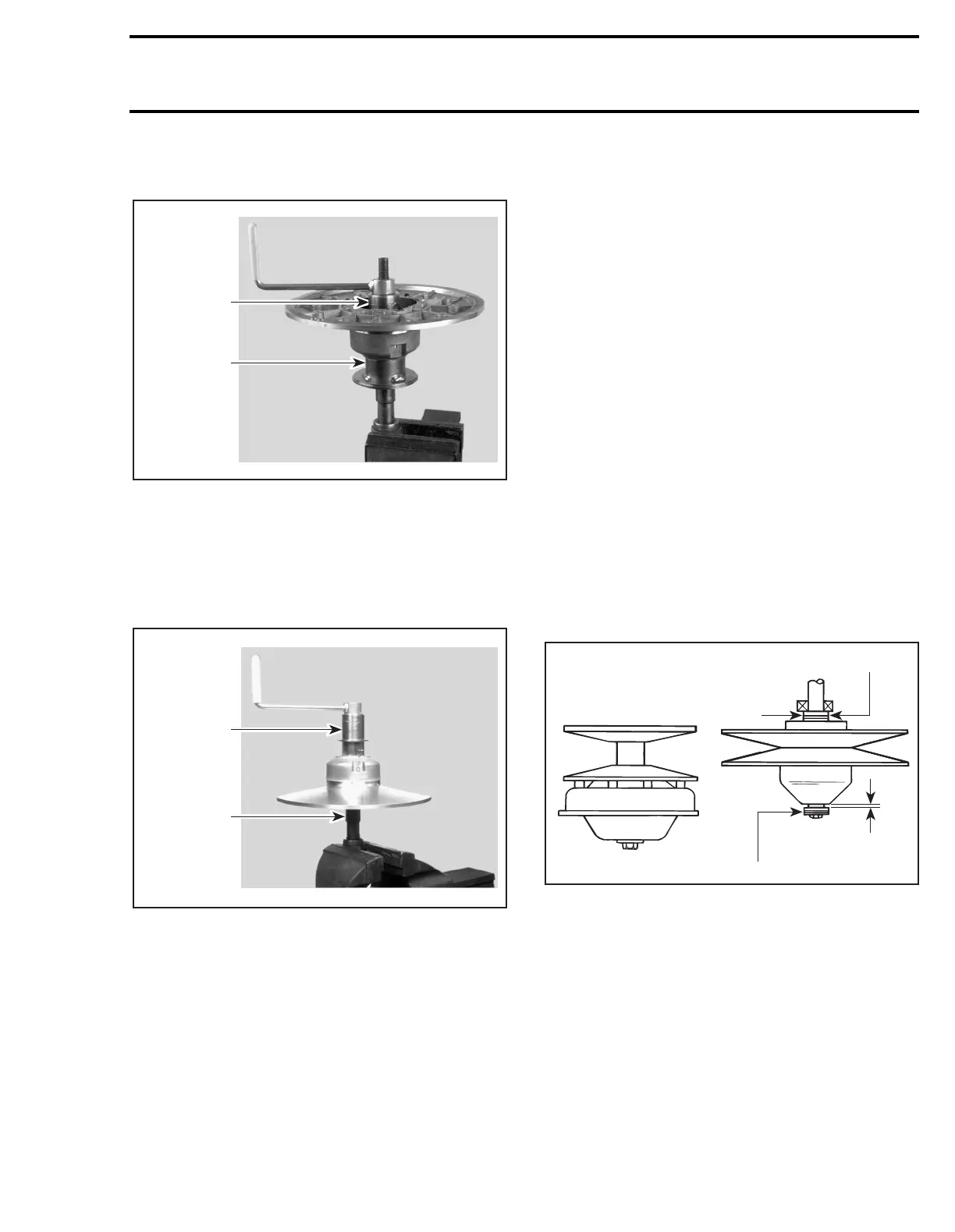
Check end play of driven pulley on countershaft
by pushing pulley towards outer housing so that
the inner shims (P / N 504 1082 00) contact it.
Measure end play at the mounting screw end be-
tween shim(s) and pulley. See illustration.
TYPICAL — TOP VIEW
1. Shim (P / N 504 1082 00) (as required)
2. Contact
A. 0 to 1 mm (0 to 3/64 in)
13, Pulley Retaining Screw
Torque to 25 N•m (18 lbf•ft).
A03D1YA
529 0313 00
529 0312 00
A03D1ZA
529 0313 00
529 0312 00
A16D0IA
1
2
A
1