Section 05 ELECTRICAL
Sub-Section 07 (TESTING PROCEDURE)
05-07-9
DUCATI CDI SYSTEM TESTING
(Applicable to 377, 443 and 503 Engine Types)
NOTE :
Ensure ignition cut-out switches are
properly working and they are in the ON po-
sition prior to performing the following tests.
WARNING : To prevent powerful electric
shocks while cranking engine, do not
touch neither electronic ignition components
(ignition coil, high tension wire, wire harness,
etc.) nor tester leads.
TRIGGER COIL OUTPUT
1. Disconnect the 4-wire connector at ignition
module.
2. Connect tester wires then set switch and dial
as follows :
3. Crank engine and observe indicator.
4. Push reset button and repeat step 3 twice.
1. Engine ground
2. White
/
Red
Results :
a.
Indicator lamp lights :
Trigger coil output is up
to specifications.
b.
Indicator lamp does not light :
The problem is
a faulty trigger coil or bad grounding.
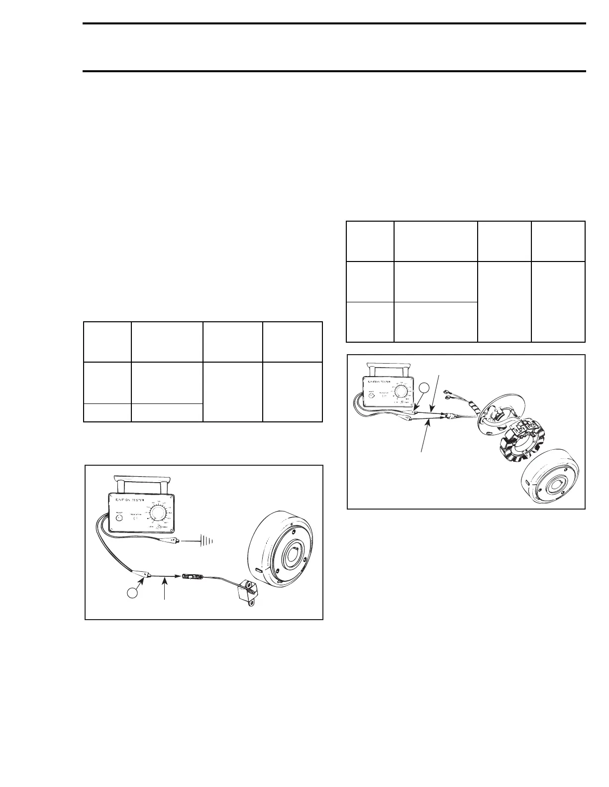
MAGNETO OUTPUT
(Ignition Generator Coil)
1. Disconnect the 4-wire connector between igni-
tion module and magneto harness.
2. Connect tester wires then set switch and dial
as follows :
1. Green
2. White
3. Crank engine and observe indicator.
4. Push reset button and repeat step 3 twice.
Results :
a.
Indicator lamp lights :
Ignition generator coil
output up to specifications.
b.
Indicator lamp does not light :
The problem is
a faulty ignition generator.
Tester
wires
Component
wires
Tester
switch
position
Tester
dial
position
N
RED
/
WHITE
wire of
trigger coil
LOW 45
P Engine ground
'
;
N
A17E0UA
1
2
Tester
wires
Component
wires
Tester
switch
position
Tester
dial
position
N
GREEN
wire of
magneto harness
LOW 80
P
WHITE
wire of
magneto harness
A17E0VA
1
2
N