Section 05 ELECTRICAL
Sub-Section 07 (TESTING PROCEDURE)
05-07-5
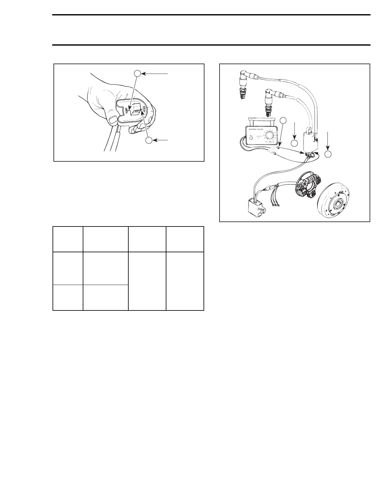
1. Black
2. White / Blue
4. Slip plastic protectors out of coil terminals.
5. Connect tester wires to coil terminals then set
switch and dial as follows :
NOTE :
If necessary use jumper wires from
coil terminals to tester wires.
TYPICAL
1. Black
2. White / Blue
6. Crank engine and observe indicator.
7. Push reset button and repeat step 6 twice.
Results :
a.
Indicator lamp lights :
Ignition module output
is up to specifications. The problem is a faulty
ignition coil.
b.
Indicator lamp does not light :
Proceed to fol-
lowing test. If magneto output tests good, the
problem is a faulty ignition module.
MAGNETO OUTPUT
(Ignition Generator Coil)
1. Disconnect the 2-wire connector between igni-
tion module and magneto harness.
At installation, secure with new locking ties.
Tester
wires
Component
wires
Tester
switch
position
Tester
dial
position
N
WHITE
/
BLUE
wire (
+
) of
ignition coil
HIGH 55
P
BLACK
wire
(−
) of
ignition coil
A00E1JA
+
_
1
2
A22E0BA
_
+
N
1
2