Section 04 TRANSMISSION
Sub-Section 06 (BRAKE)
04-06-7
Apply anti-seize lubricant (P / N 413 7010 00) on
shaft and check that disc slides freely.
The disc hub exceeds the disc more from one
side than from the other. Install disc with the long-
er exceeding portion toward driven pulley.
Push O-rings inside disc hub.
Countershaft Bearing Adjustment
S-Series
Insert countershaft (with brake disc) from chain-
case side through countershaft support (driven
pulley side), then insert into chaincase.
Install countershaft bearing
no. 19
and ensure
that countershaft is properly aligned, then tighten
3 retaining screws.
NOTE :
A misaligned countershaft will result
in difficulty to center the bearing in its sup-
port.
Refer to DRIVE AXLE 06-04 then look
Chaincase
Perpendicularity Adjustment.
Torque castellated nut of upper sprocket to 53
N•m (39 lbf•ft).
CAUTION : Upper sprocket castellated nut
must be tightened
before
adjusting bearing
collar.
Slide collar
no. 18
towards bearing and turn, by
hand, to engage the eccentric. This should require
about a quarter turn.
Turn collar in direction of countershaft rotation un-
til collar and inner race lock together.
Insert a punch into collar hole and strike sharply in
the same direction to lock firmly.
Apply Loctite 242 (P / N 413 7030 00) on set
screw threads, then tighten.
Close chaincase referring to CHAINCASE 04-07.
1,11,12, Locking Tab, Outer Caliper
and Nut
S-Series
Install caliper retaining bolts.
Assemble outer caliper. Install locking tab then
nuts. Torque nuts to 24 N•m (18 lbf•ft). Bend lock-
ing tab over a flat of each nut.
5,10, Brake Cable and Nut
Insert brake cable into upper hole in brake lever
and caliper. Install nut and tighten until a few
threads exceed.
WARNING : At least 3 threads must ex-
ceed the elastic stop nut.
ADJUSTMENT
Brake
Models with Mechanical Brake
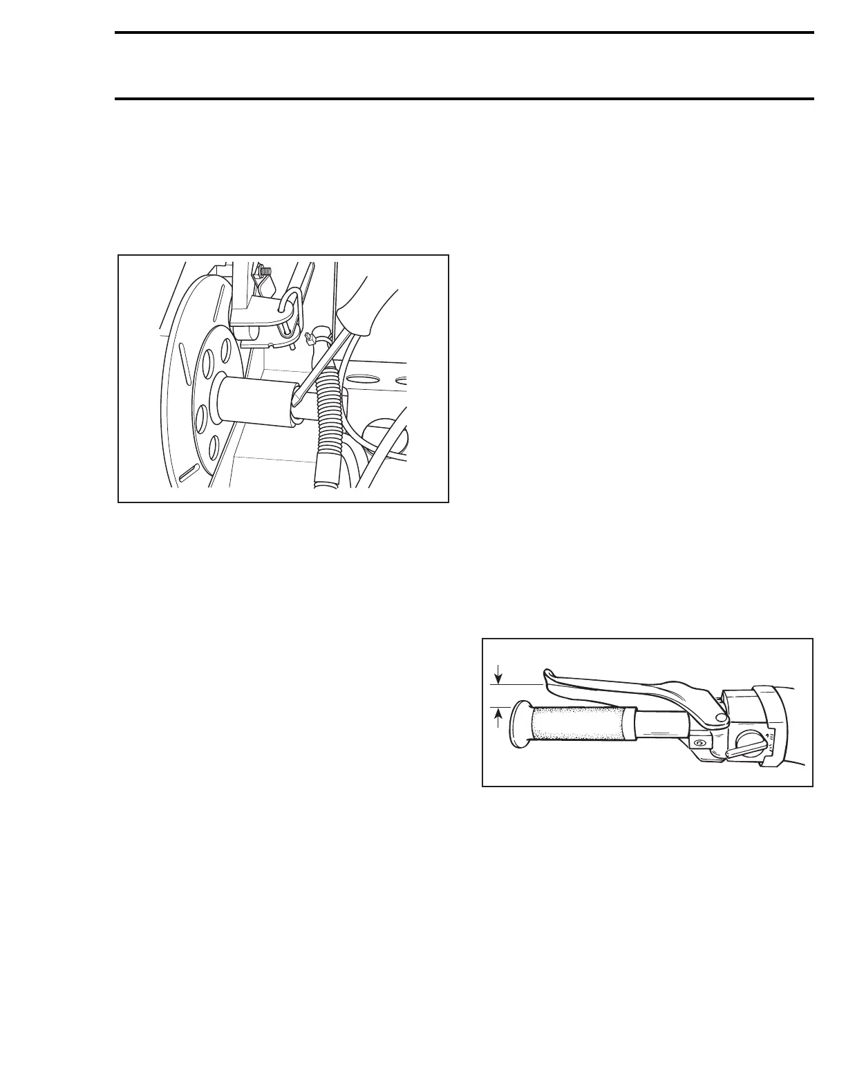
Fully depress brake handle several times to obtain
13 mm (1/2 in) between brake handle and handle-
bar grip when brake is fully applied.
A. 13 mm (1/2 in)
Should this adjustment be unattainable, retighten
nut
no. 10
as needed.
Models with Hydraulic Brake
Change brake fluid once a year.
Bleed brake system as follows :
Keep sufficient DOT 4 (DOT 3 for normal use)
brake fluid in reservoir at all times.
CAUTION : Use only DOT 4 brake fluid for
heavy duty or racing applications.
A03D13A
;
A08G02A
A