Section 06 REAR SUSPENSION
Sub-Section 02 (TORQUE REACTION SUSPENSION)
06-02-2
COMPONENT REMOVAL
Lift rear of vehicle and support it off the ground.
5, Rear Arm
Release spring tension. Unfasten shock from rear
arm. Remove 3 screws retaining rear arm.
REMOVAL
NOTE :
To prevent cross shaft from turning
when unscrewing screws assembled with
threadlocker, proceed as follows :
– Loosen one screw then retighten.
– Remove the other screw.
– Remove the first one.
1,2,3,4, Cross Shaft, Idler Wheel,
Spacer and Screw
Remove idler wheel ass’y.
Lift rear of vehicle and support it off the ground.
Unscrew 4 screws retaining front arm and rear
arm to frame.
Remove suspension.
DISASSEMBLY AND ASSEMBLY
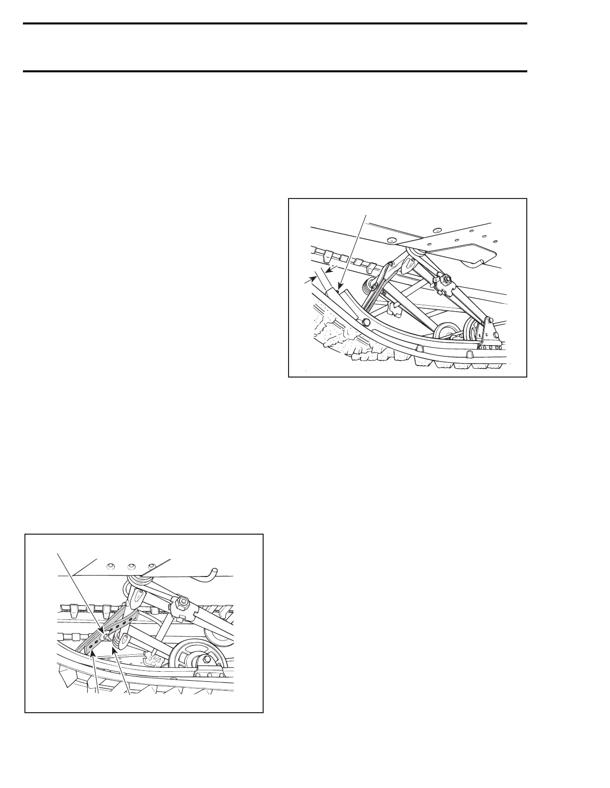
6, Stopper Strap
Inspect strap for wear or cracks, bolt and nut for
tightness. If loose, inspect hole for deformation.
Replace as required. Make sure it is attached
through the 3
rd
hole from the end. Torque nut to
11 N•m (97 lbf•
in
).
1. 1
st
hole
2. 3
rd
hole
A. 11 N•m (97 lbf•in)
9,10,12, Nut, Slotted Screw and Slider
Shoe
To replace a worn shoe, remove the front screw
and stop nut, then slide the shoe rearward out of
the runner.
NOTE :
Slider shoe minimum thickness : 10
mm (25/64 in).
1. Front screw and nut
A. 10 mm (25/64 in)
CAUTION : Slider shoes must always be
replaced in pairs.
7,8, Support and Front Arm Support
To remove rivets securing the supports, cut rivet
heads off using a cold chisel.
At assembly, position the rivet head toward the
outside of the assembly. Support the rivet head
against a metal block, as shown, and use a flat
head punch to secure the rivet in place.
'
A05F0CA
A
12
A05F0IA
1
A