Section 04 TRANSMISSION
Sub-Section 04 (DRIVEN PULLEY)
04-04-10
ADJUSTMENT
Refer to PULLEY DISTANCE AND ALIGNMENT
04-05 to adjust pulley distance. Adjust drive belt
height between pulley halves to obtain specified
belt deflection.
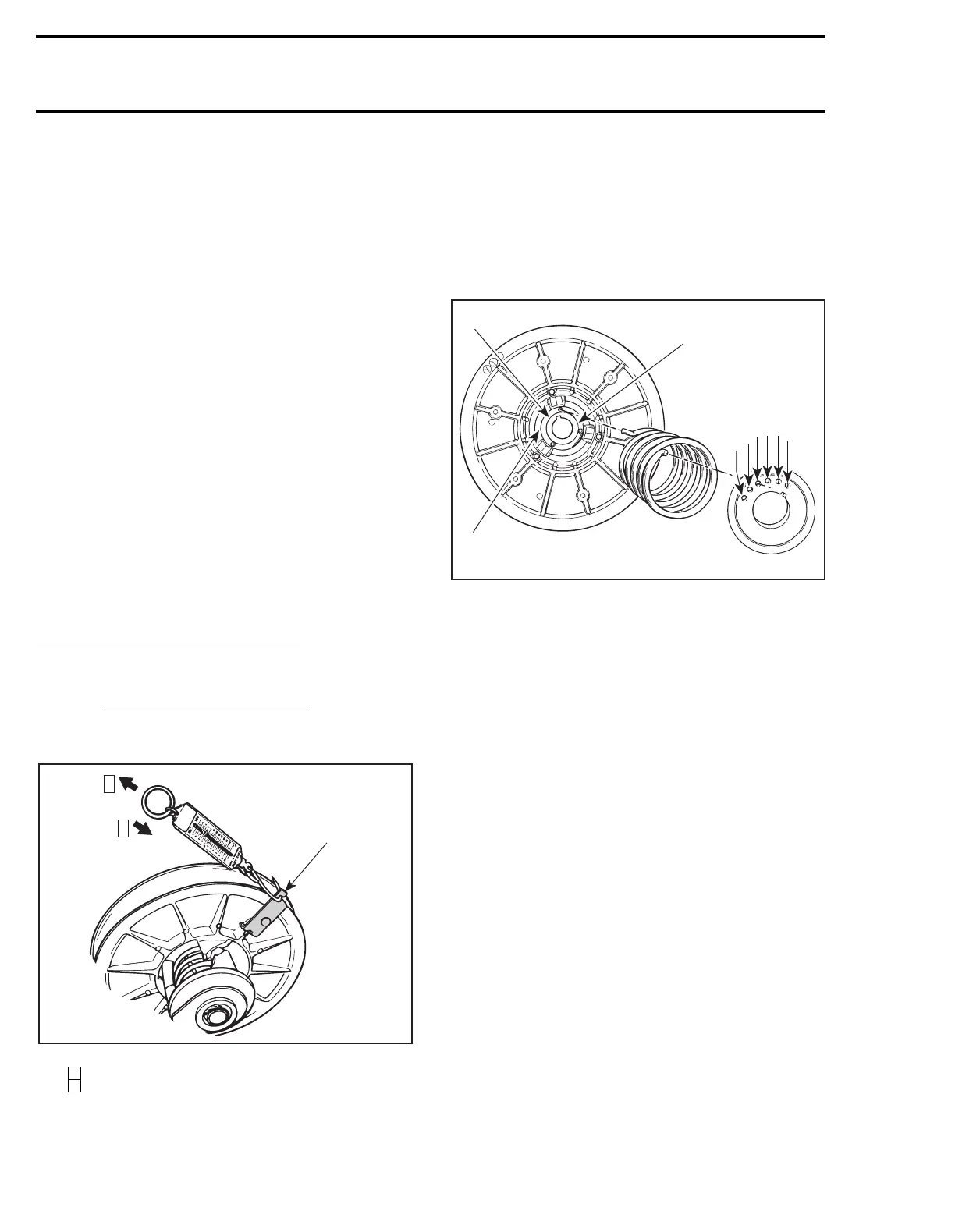
5, Spring
Spring Torsional Pre-Load
To check spring pre-load adjustment, use spring
scale hook (P / N 529 0065 00) and a spring scale.
Remove drive belt.
Install the hook on the sliding half. Preventing
fixed half from turning, pull sliding half with the
spring scale perpendicularly with pulley axle.
Take 1
st
measurement when sliding half begins to
turn. Rotate sliding half to 10 mm (3/8 in) of rota-
tion. Hold fish scale at this position. Slowly re-
lease tension from fish scale and take 2
nd
measurement when sliding half begins to return.
Spring pre-load is the average measurement be-
tween these 2.
TYPICAL
Step : 1
st
measurement
Step : 2
nd
measurement
To adjust spring pre-load, relocate spring end in
cam, moving it clockwise to increase the pre-load
and counterclockwise to decrease it. Refer to
TECHNICAL DATA 09-03.
NOTE :
If spring pre-load can not be adjust-
ed, try to relocate the other end of spring in
sliding pulley (holes A, B, C).
Letters and numbers shown in illustration are actual letters and
numbers embossed on parts
NOTE :
Always recheck torsional pre-load
after adjusting.
Pulley Alignment and Drive Belt
Deflection
Refer to PULLEY DISTANCE AND ALIGNMENT
04-05 and DRIVE BELT 04-02 to perform adjust-
ments.
CAUTION : Drive belt and pulley adjustments
must always be checked whenever pulleys
have been removed, replaced or disassembled.
3, Outer Cam
Make sure to install proper cam. Refer to TECHNI-
CAL DATA 09-03.
Cam angle is identified on cam.
1
st
measurement
(when opening)
+
2
nd
measurement
(when closing)
=
Spring
pre-load
2
Example :
3.8 kg (8.4 lb)
(when opening)
+
3.4 kg (7.5 lb)
(when closing)
=
3.6 kg (8 lb)
Actual
spring
pre-load
2
529 0065 00
A01B18A
1
2
1
2
'
A18C0AA
32
1
4
5
6
A
C
B