Section 05 ELECTRICAL
Sub-Section 07 (TESTING PROCEDURE)
05-07-4
NIPPONDENSO CDI SYSTEM TESTING
(Applicable to 277 Engine Type)
NOTE :
Ensure ignition cut-out switches are
properly working and they are in the ON po-
sition prior to performing the following tests.
WARNING : To prevent powerful electric
shocks while cranking engine, do not
touch neither electronic ignition components
(ignition coil, high tension wire, wire harness,
etc.) nor tester leads.
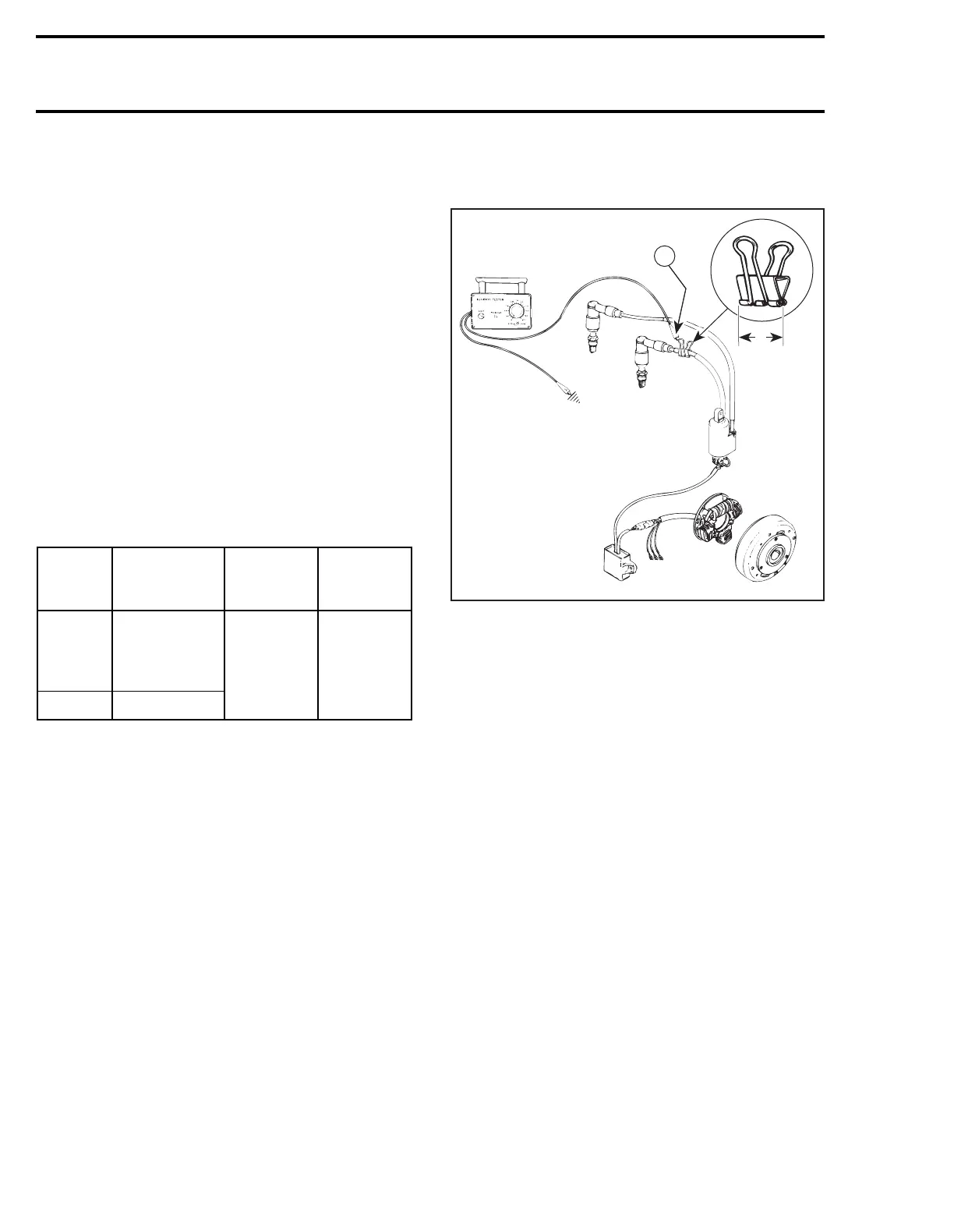
IGNITION COIL OUTPUT
A paper clip of approximately 20 mm (3/4 in) will
be used as a test adapter for the following test.
1. Clip the test adapter around spark plug cable
close to the spark plug.
2. Connect tester wires then set switch and dial
as follows :
TYPICAL
1. Engine ground
2. MAG side
A. 20 mm (3/4 in)
3. Crank engine and observe indicator.
NOTE :
If engine starts, allow it to idle while
observing indicator. Then, shut engine off.
4. Push reset button and repeat step 3 twice.
Results :
a.
Indicator lamp lights :
Ignition system is OK.
b.
Indicator lamp does not light on one or both
cylinder :
Proceed to following tests.
IGNITION MODULE OUTPUT
1. Disconnect both connectors at ignition coil.
At installation, secure with new locking ties.
2. Connect an ignition coil (known as being in
good condition) to the spark plug.
3. Connect CDI module to replacement ignition
coil paying attention to connect the WHITE /
BLUE wire to the positive (+) terminal and the
BLACK wire to the negative (–) terminal.
Tester
wires
Component
wires
Tester
switch
position
Tester
dial
position
N
Tester adapter
(paper clip)
on spark plug
cable
LOW 45
P Engine ground
'
;
N
A
A22E0AA
N
21
'