Section 03 ENGINE
Sub-Section 06 (OIL INJECTION SYSTEM)
03-06-3
OIL PUMP IDENTIFICATION
Different engines need different pumps. See
identification on pump lever
no. 7
.
CAUTION : Always mount proper pump
on engine.
NOTE :
The following procedures can be
done without removing the engine from
chassis.
CLEANING
Clean all metal components in a non-ferrous met-
al cleaner.
DISASSEMBLY
NOTE :
Some oil pump components are not
available as single parts.
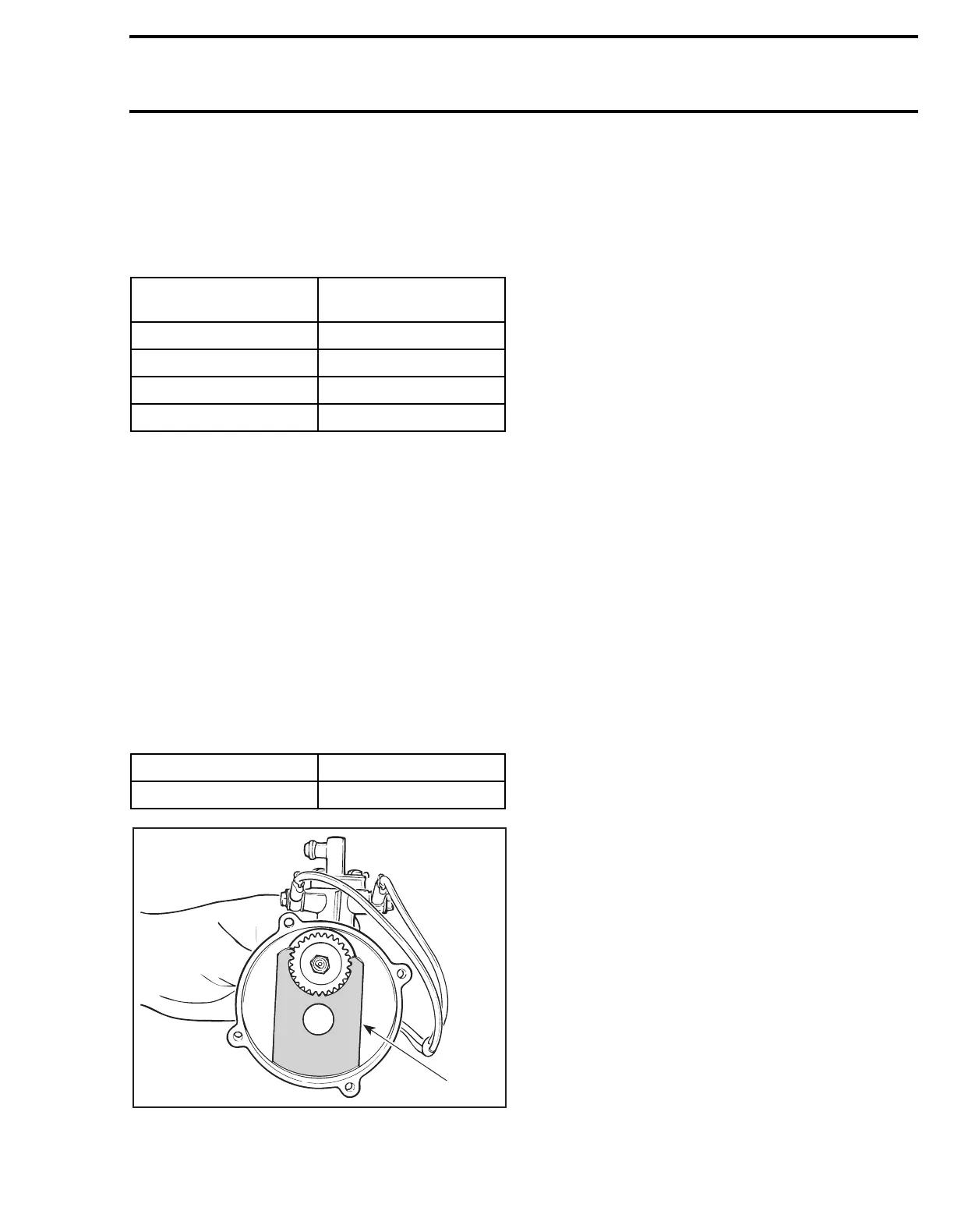
To remove gear retaining nut
no. 1
, first extract
the needle roller
no. 4
with pliers then lock gear
no. 2
in place using the following gear holder :
ASSEMBLY
At gear
no. 2
assembly, apply a light coat of low
temperature grease (P / N 413 7061 00) on gear
teeth.
The needle roller
no. 4
must be engaged as deep
as possible in the pump mounting flange.
Always check for spring clips
no. 5
and clamps
no. 6
tightness.
Torque screws
no. 3
to
5 N•m (44 lbf•
in
).
Make sure cable barrel is well seated in oil pump
lever.
Secure barrel with plastic washer and circlip.
Verify cable and oil pump lever operation.
ADJUSTMENT
Prior to adjusting the pump, make sure all carbu-
retor adjustments are completed.
Synchronizing Pump with Carburetor :
Eliminate the throttle cable free-play by pressing
the throttle lever until a light resistance is felt,
then hold in place. The aligning marks on the
pump casting and on the lever must align. If not,
loosen the adjuster nut and adjust accordingly.
ENGINE TYPE
OIL PUMP
IDENTIFICATION
277 135 T
377 L4
443 E4
503 E4
ENGINE TYPE TOOL P / N
377 / 443 / 503 420 8766 95
A10C01A
420 8766 95