03-2
Section 03 ELECTRICAL SYSTEM
Ignition System — MPEM Module
(Multi-Purpose Electronic Module)
This module operates on direct current (12 VDC).
MPEM
1. PTO high tension coil; 3-05 housing
2. CENTRE high tension coil; 3-04 housing
3. MAG high tension coil; 3-03 housing
4. Trigger coil; 2-03 housing
5. Positive supply; 2-03 housing
6. Ground, buzzer, warning light, signal to DPM, engine shut-off;
3-06 housing
7. DESS switch
8. Load breaker
The 360-watt magneto has no ignition generator
coil. All the ignition current comes from the mag-
neto coil. A BLACK/YELLOW wire allows the en-
gine to stop. Grounding this wire will short-circuit
the ignition module.
Trigger coil pulses are sent to the module in order
to ignite the spark plug at the right time.
1. Trigger coil wires; 2-03 housing
This device includes the DESS system. See sec-
tion 3.
This module also activates the warning buzzer (re-
verse and DESS code).
Finally, the MPEM controls load supply (head-
lamp, taillight, dashboard gauges, heated compo-
nents, etc.). If the key is left in the ON position
without the engine running, the MPEM will not
supply current to the loads, and this to prevent
discharging of the battery. The MPEM will only al-
low the loads to be fed (20A fuse, through
RED/YELLOW wire) if the engine revolution ex-
ceeds 800 RPM.
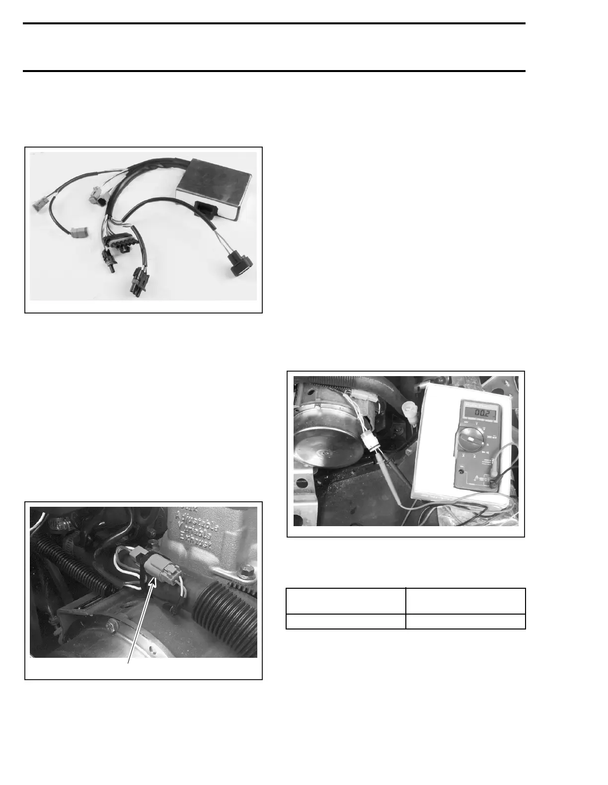
TESTING PROCEDURE
Magneto
Coil Testing
NOTE:
The coil being triple, all 3 parts must be
tested separately. Refer to the electrical diagram
at the end of this supplement.
Connect an ohmmeter to the magneto YELLOW/
YELLOW wires (2-04A, 2-04B and 2-04C).
The resistance must be as indicated in the follow-
ing table. All 3 sections of the coil have the same
resistance.
Coil Insulation Test
Disconnect 2-01 housing.
NOTE:
Disconnect WHITE/GREEN wire (2-01-2)
before testing coil insulation. Otherwise, the mag-
neto coil remains connected to the tachometer
and the reading will be false.
Disconnect 2-04 magneto outlet.
A00E4YA
1
2
3
4
6
5
7
8
A00I08A
1
WIRES
RESISTANCE VALUES
Ω
YELLOW and YELLOW maximum 0.5
A06E2RA