Section 04 TRANSMISSION
Sub-Section 03 (DRIVE PULLEY)
04-03-10
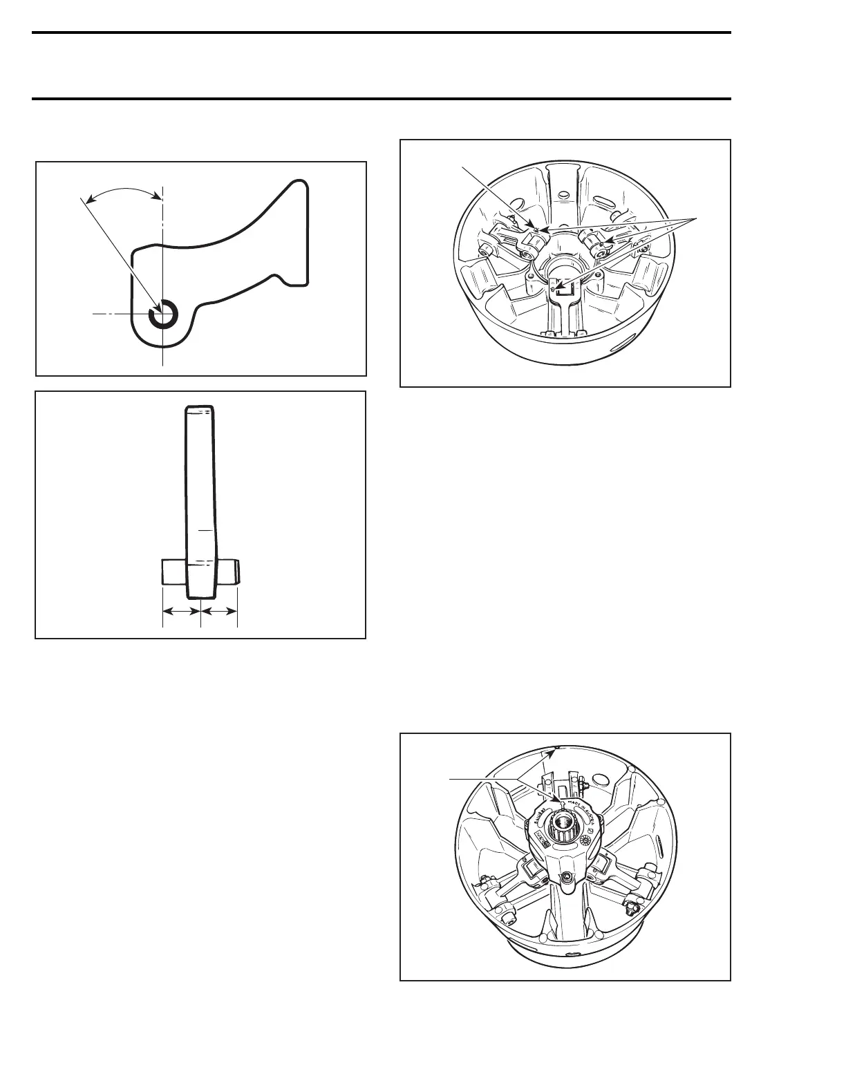
Position dowel tube split at the illustrated angle.
1. Equal distance
Torque screws to 10 N•m (89 lbf•
in
).
9,11,13,14, Screw, Lever Ass’y, Nut and
Cotter Pin
Always install lever assemblies so that cotter pins
are at the shown side. Besides install cotter pin
head on top when lever is sat at bottom of sliding
half. Bend cotter pin ends to sit perfectly against
lever.
WARNING : Whenever replacing centrifu-
gal levers, always replace all 3 at the
same time. Otherwise, clutch misbalancing
will occur because of levers difference.
1. Head on top
2. All on the same side
CAUTION : Lever assemblies must be in-
stalled so that cotter pins are on the same
side.
Torque nuts to 12 N•m (106 lbf•
in
).
CAUTION : Lever ass’y and rollers must
move easily after installation.
5,6,18,19, Fixed Half, Sliding Half, Spring,
Spring Cover and Screw
To install spring cover, use spring compressor (P / N
529 0151 00).
Assemble fixed and sliding halves. Note that fixed
halves have different cone angle. Match cone an-
gle with crankshaft.
Lift sliding half against spring cover and align
spring cover arrow with sliding half mark.
1. Align
Install and torque screws to 10 N•m (89 lbf•
in
).
A16D2PA
30 ± 5°
A16D09A
11
;
A16D0BA
1
2
A16D0DA
1