Section 03 ENGINE
Sub-Section 02 (443 AND 503 ENGINE TYPES)
03-02-8
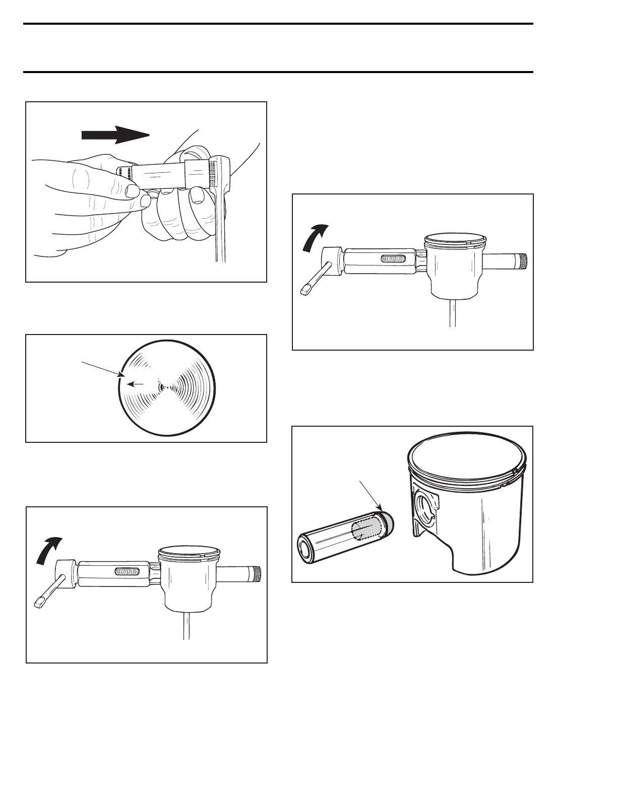
– Mount piston over connecting rod with the let-
ters “AUS” (over an arrow on the piston dome)
facing in the direction of exhaust port.
1. Exhaust
– Install piston pin puller (P/N 529 0210 00) and
turn handle until piston pin is correctly posi-
tioned in piston.
– Remove piston pin puller and expansion
sleeve.
– Install circlips as described below.
– When installing new needle bearing, insert
needles with thrust washers. Instead of expan-
sion sleeve, needles are held in place by 2 inner
plastic cage halves.
– Use piston pin puller (P/N 529 0210 00) to insert
piston pin. Plastic halves should come off pis-
ton. If not, pull them out using long nose pliers.
– Install circlips as described below.
503 Engine
To center the piston pin with the connecting rod
bearing, use centering tool (P/N 529 0091 00).
NOTE:
The circlip on the opposite side can
be installed before pin installation, the tool
will easily go out.
All Engines
To minimize the effect of acceleration forces on
circlip, install each circlip so the circlip break is at
6 o’clock as illustrated. Use piston circlip installer
(P/N 529 0086 00).
A21C02A
A01C01A
AUS
1
A21C01A
A21C01A
A01B1SA
529 0091 00