Section 03 ENGINE
Sub-Section 03 (454, 494, 583 AND 670 ENGINE TYPES)
03-03-8
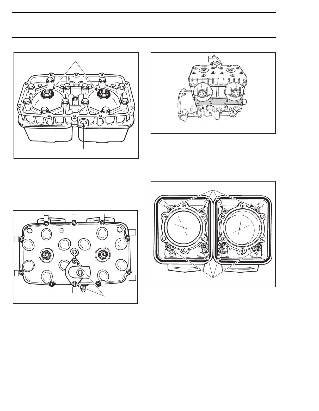
TYPICAL
1. O-rings
2. Temperature sensor hole
A. Torque to 29 N•m (21 lbf•ft)
1, Screw
Torque cylinder head cover screws to 10 N•m (90
lbf•
in
) as per following illustrated sequence.
TYPICAL
1. Longer screws
454, 583 and 670 Only
When reassembling the cylinders to the crank-
case, it is important to have them properly aligned
so that the cylinder head holes will match up with
the studs. Cylinder head itself can be used to align
the cylinders. Prior to torquing crankcase/cylinder
nuts, install exhaust manifold to properly align ex-
haust flanges or use exhaust flange aligning tool
(P/N 420 8769 02).
Apply Loctite 242 (P/N 413 7030 00) on cylinder
screw threads.
Install and torque screws in a criss-cross se-
quence for each cylinder to 29 N•m (21 lbf•ft). For
454 and 670 engines longer screws go on exhaust
side.
TYPICAL
A. Torque screws to 29 N•m (21 lbf•ft)
17, Gasket
583 Only
Install gasket with its larger holes on exhaust side.
A25C0CA
1
2
A
A25C0DA
1
9
8
4
2
6
10
11
7
35
A24C0NA
420 8769 02
F01D13A
A
A