Section 03 ENGINE
Sub-Section 09 (ROTARY VALVE, COOLANT PUMP AND RESERVOIR)
03-09-7
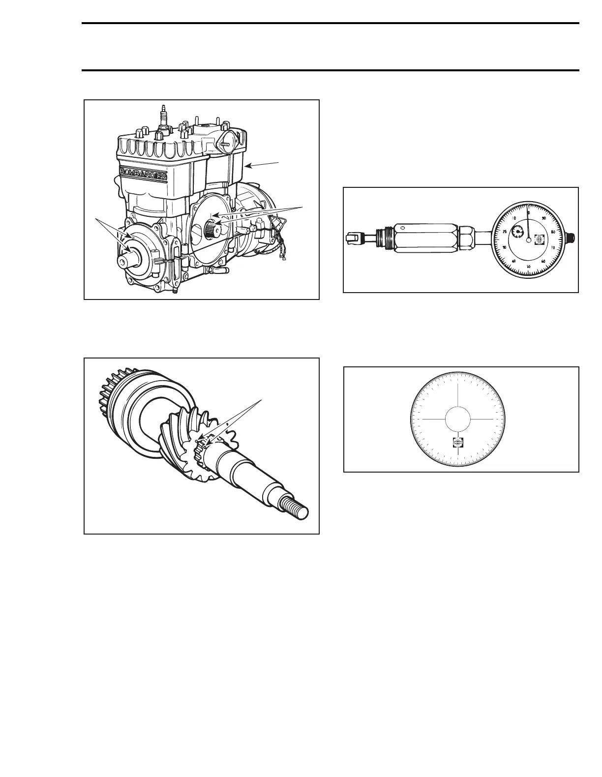
1. Mark here
2. MAG piston at TDC
After removing rotary valve shaft but before disas-
sembling, mark brass gear in relation to shaft.
1. Mark here
These marks will be useful to time rotary valve ex-
actly to the specifications.
NOTE:
Tolerance of rotary valve timing is ± 5
degrees.
When the same crankcase is reassembled, the
first timing method is to be followed. However
since replacement crankcases do not have timing
marks (ridge), the second method is required.
Take note that the second method is more accu-
rate and may be used any time.
Installation
To correctly install rotary valve, proceed as fol-
lows:
– Turning crankshaft, bring
MAGneto side
piston
to Top Dead Center.
Use a dial indicator (P/N 414 1047 00).
A degree wheel (P/N 414 3529 00) is required to
measure rotary valve opening and closing angles
in relation with
MAGneto side
piston. Degree
wheel will be installed on rotary valve shaft for
measurements.
Rotary valve must be set as specified in TECHNI-
CAL DATA 09.
For the following instructions, use these specifi-
cations as example:
OPENING: 132° BTDC
CLOSING: 52° BTDC
Proceed as follows:
– Turning crankshaft, bring
MAGneto side
piston
to Top Dead Center as done before with a
crankcase having a ridge.
– For opening mark, first align 360° line of degree
wheel with BOTTOM of
MAGneto side
inlet
port. Then, find 132° line on degree wheel and
mark crankcase at this point.
A16C16A
1
2
1
A16C17A
1
A00B2EA
414 1047 00
3
6
0
3
5
0
3
4
0
3
3
0
3
2
0
3
1
0
3
0
0
2
9
0
2
8
0
2
7
0
2
6
0
2
5
0
2
4
0
2
3
0
2
2
0
2
1
0
2
0
0
1
9
0
1
8
0
1
7
0
1
6
0
1
5
0
1
4
0
1
3
0
1
2
0
1
1
0
1
0
0
9
0
8
0
7
0
6
0
5
0
4
0
3
0
2
0
1
0
1
0
2
0
3
0
4
0
5
0
6
0
7
0
8
0
9
0
1
0
0
1
1
0
1
2
0
1
3
0
1
4
0
1
5
0
1
6
0
1
7
0
1
8
0
1
9
0
2
0
0
2
1
0
2
2
0
2
3
0
2
4
0
2
5
0
2
6
0
2
7
0
2
8
0
2
9
0
3
0
0
3
1
0
3
2
0
3
3
0
3
4
0
3
5
0
3
6
0
A00B33A