Section 05 ELECTRICAL
Sub-Section 03 (IGNITION TIMING)
05-03-3
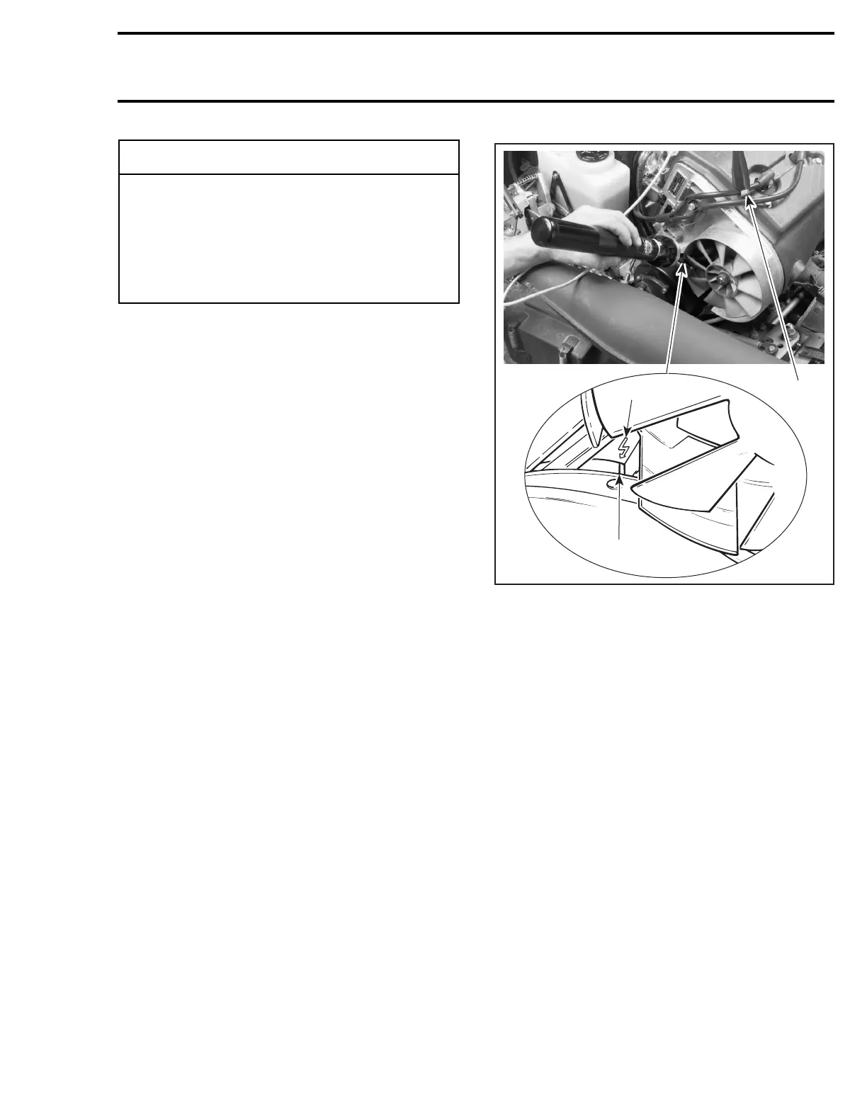
1. Connect the timing light pick-up to a spark plug
cable and the power connections to the battery.
NOTE:
To avoid an incorrect reading due to
parallax, view the magneto flywheel and the
crankcase timing marks in a straight line.
2. Start the engine and raise the engine speed at
least to 2000 RPM while observing the timing
marks, refer to illustration. The magneto fly-
wheel mark scribed previously and the crank-
case arrow should be perfectly aligned. If the
marks do not align, a faulty trigger coil (check
proper grounding of coil) or a faulty CDI module
could be the cause: substitute one part at a
time and recheck timing marks (check connec-
tors condition prior to substituting any part).
NOTE:
Ignition timing may be verified when
engine speed is anywhere within 2000-6000
RPM.
CHECKING IGNITION TIMING
1. Timing light pick-up on MAG side
2. Crankcase arrow
3. Magneto flywheel mark
3. Install parts which were removed.
◆
WARNING
Place ski tips against a wall, raise rear of ve-
hicle on a stand, so that track does not con-
tact the ground. Do not allow anyone in front
of or behind the vehicle while engine is run-
ning. Keep clear of track and do not wear
loose clothing which can get caught in mov-
ing parts.
A03E1EA
2
3
1