Section 03 ENGINE
Sub-Section 08 (CARBURETOR AND FUEL PUMP)
03-08-6
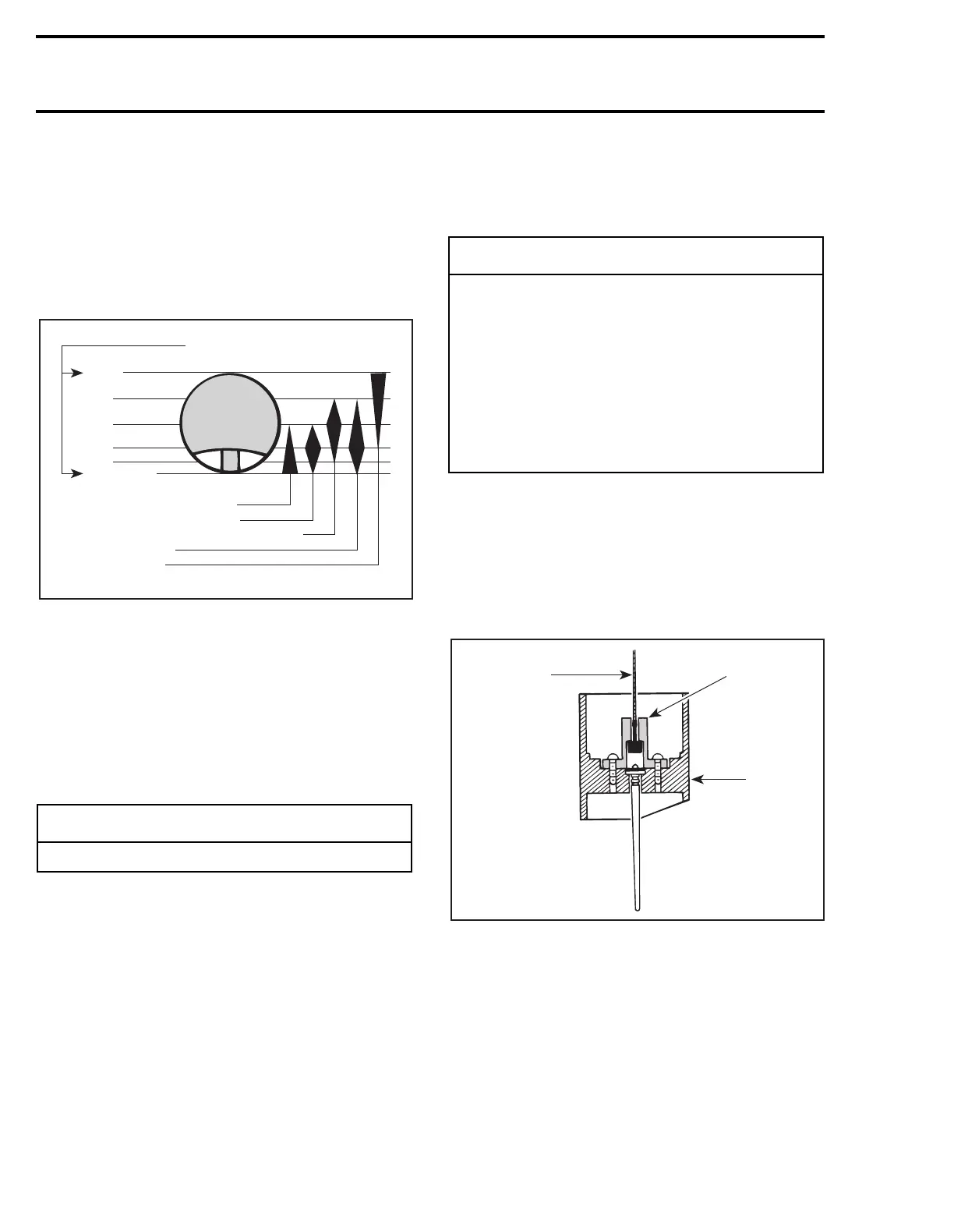
The following illustration shows the part of the
carburetor which begins and stops to function at
different throttle slide openings.
Note that the wider part of symbol corresponds to
the opening mostly affected. For instance, throt-
tle slide cut-away begins to function at closed po-
sition but it is most effective at 1/4 opening and
decreases up to 1/2 opening.
VIEW FROM AIR INTAKE OPENING
NOTE:
For fine tuning refer to TECHNICAL DATA
09-02 and to SPARK PLUG 05-03.
NOTE:
For high altitude regions, the
High Altitude
Technical Data Booklet
(P/N 484 0648 00 and 484
0545 00 for binder) gives information about cali-
bration according to altitude and temperature.
INSTALLATION
To install carburetor on engine, inverse removal
procedure.
However, pay attention to the following:
– Inspect throttle cable and housing prior to in-
stallation.
On applicable models, make sure to align tab of
carburetor and air intake silencer (if applicable)
with notch of adaptor(s). On applicable models, in-
stall adaptor with up mark facing up.
Install clamps in a way that their tightening bolts
are staggered — not aligned.
Hook throttle cable into the needle retainer plate.
NOTE:
Do not obstruct hole in throttle slide when
installing needle retaining plate. This is important
to allow air escaping through and thus allowing a
quick response.
CENTER POST TYPE
1. Throttle cable
2. Needle retaining plate
3. Throttle slide
-
CAUTION
Never allow throttle slide(s) to snap shut.
Throttle slide openings
Wide
open
3/4
1/2
1/4
1/8
Close
Pilot jet and air screw13,6,
Throttle slide cutaway5,
Needle taper and needle position3,
Needle jet14,
Main jet8,
A00C04A
-
CAUTION
The rubber flange must be checked for
cracks and/or damage. At assembly, the
flange must be perfectly matched with the
air intake manifold or severe engine damage
will occur. Beside do not interchange carbu-
retors, the jetting may be different on each
side. A red dot is printed on MAG carburetor
(blue on PTO side) and on the high tension
coil support. Match the carburetor and the
support dots.
A00C1TA
1
2
3