Section 05 ELECTRICAL
Sub-Section 05 (TESTING PROCEDURE)
05-05-5
MAGNETO OUTPUT
(IGNITION GENERATOR COIL)
1. Disconnect the 3-wire connector between igni-
tion module and magneto harness.
At installation, secure with new locking ties.
2. Connect tester wires then set switch and dial
as follows:
TYPICAL
3. Crank engine and observe indicator.
4. Push reset button and repeat step 3 twice.
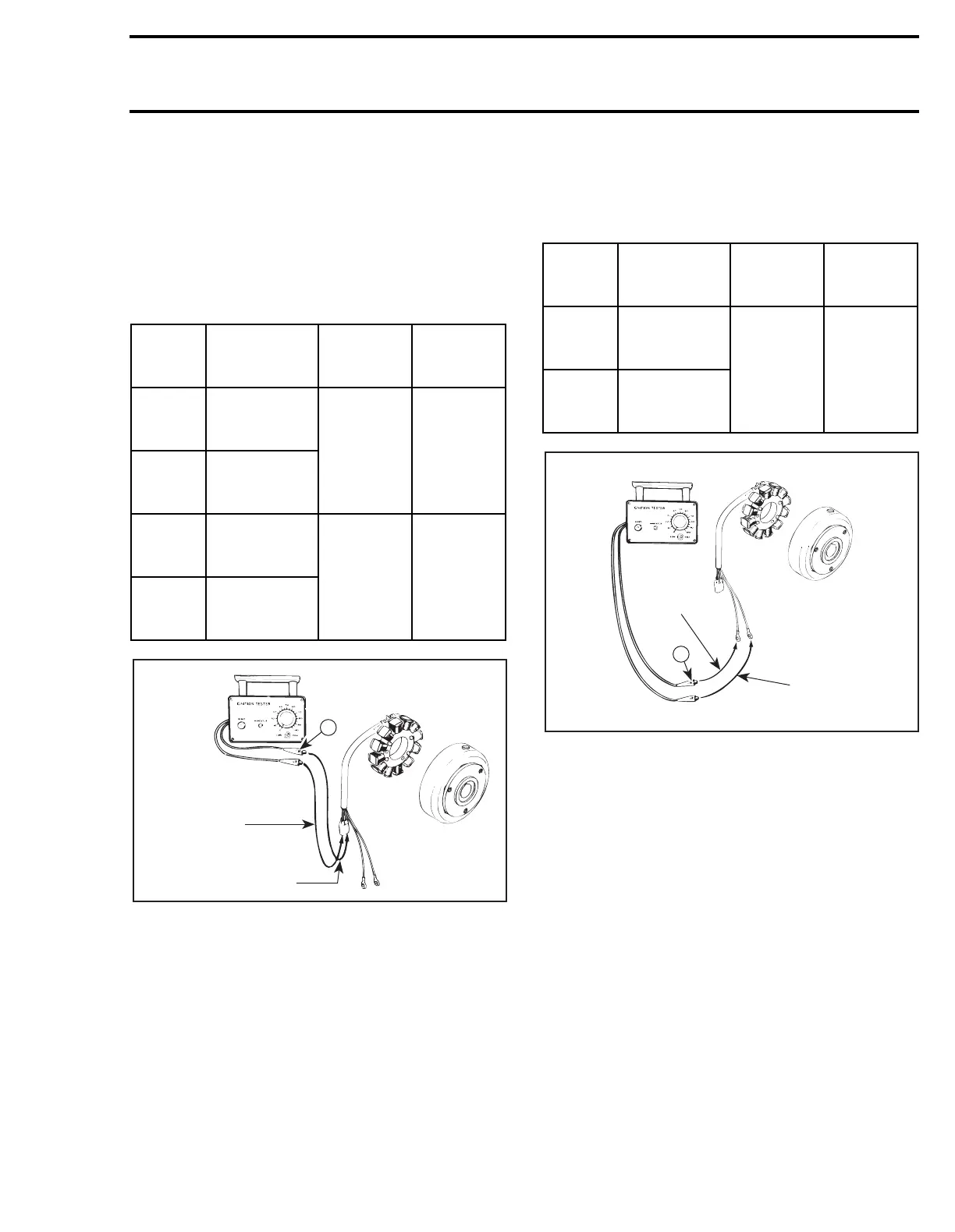
LIGHTING GENERATOR COIL
OUTPUT
NOTE:
The lighting generator coil is not part of
the ignition system. It is a separate system that
supplies current to the lighting system and AC-
powered devices. However it can be tested with
the same tester.
1. Disconnect wiring harness junction block at en-
gine (the one with YELLOW wires).
2. Connect tester wires then set switch and dial
as follows:
3. Crank engine and observe indicator.
4. Push reset button and repeat step 3 twice.
Results:
a.
Indicator lamp lights:
Lighting generator
coil output is up to specifications.
b.
Indicator lamp does not light:
Lighting gen-
erator coil is faulty.
Tester
wires
Component
wires
Tester
switch
position
Tester
dial
position
N
WHITE
wire of
magneto harness
LOW 75
P
BLACK / RED
wire of
magneto harness
N
WHITE
wire of
magneto harness
LOW 85
P
RED
wire of
magneto harness
N
A15E0UA
Red
Black/Red
Tester
wires
Component
wires
Tester
switch
position
Tester
dial
position
N
YELLOW
wire of
magneto harness
LOW 75
P
YELLOW
wire of
magneto harness
N
Yellow
A15E0VA
Yellow