08-3
Section 08 WIRING DIAGRAM
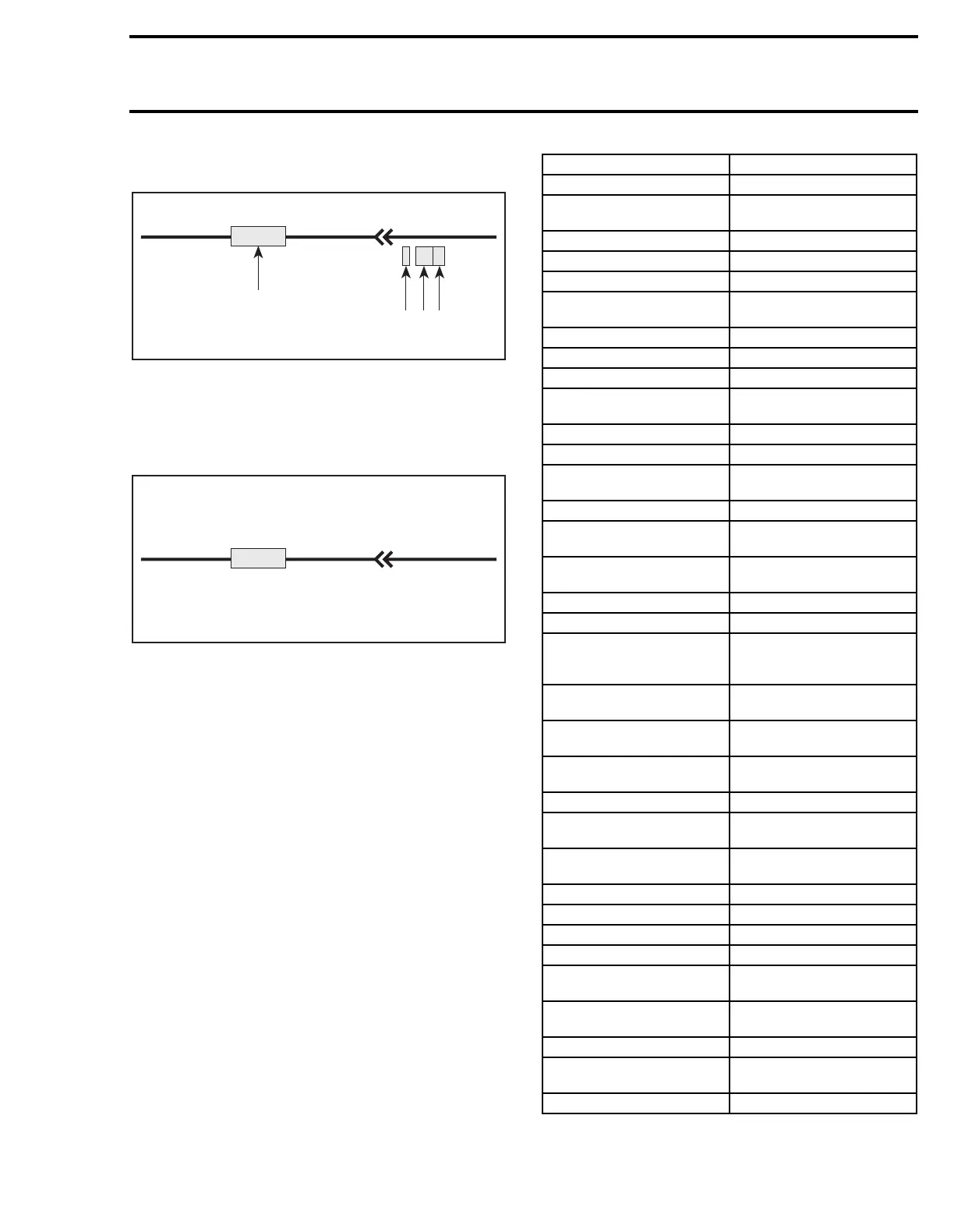
WIRING DIAGRAM LEGEND
1. Wire colors
2. Housing area
3. Housing number per area
4. Wire connector location in housing
WIRE COLORS AND CIRCUIT
A00I04A
XX/XX
1-02D
1
2 3 4
A00I04B
XX/XX
1-02D
CODE CIRCUIT
WH Rear brake light
WH/BL
Ignition: between CDI and
coils
WH/GY Safety lanyard cap
WH/YL Trigger coil wire no. 1
WH/BK DESS pilot lamp (-)
WH/GN
Magneto output/360-W
tachometer signal
TA/BK Back-up alarm
TA Back-up alarm switch
BR Heated lever
BL
Fuel level sender; DPM
enrichment switch
BL/YL Trigger coil wire no. 2
GY High beam
GY/GN
Engine speed signal from
ADC to DPM
GY/VI Low beam
YL
Alternating current supply
AC +
YL
Direct current supply; rear
light and heated grip
YL/BR Compressor
YL/GN Release valve
BK
Engine ground, frame, DC
battery-, enrichment switch
ground, DPM
BK/WH
Engine stopping: closed
ignition ON
BK/YL
Engine stopping; opened
ignition ON
BK/GN
Digital signals ground: ROM
key
OR Heated grips
RD
DC + battery, DPM
enrichment switch supply
RD/WH
DC +: 30A fuse, DPM
compensation solenoid
RD/BL DC + regulator output
RD/GY DPM supply
RD/YL Loads supply
RD/OR Compressor supply
RD/GN
Starter solenoid, DPM
enrichment solenoid
RD/VI
DPM fuses, compressor and
discharge plunger supply
GN Coolant temperature (gauge)
VI
Coolant temperature, DPM
coolant temperature (binary)
VI/WH Air intake temperature