CD600 Plus - User’s Manual
3.4
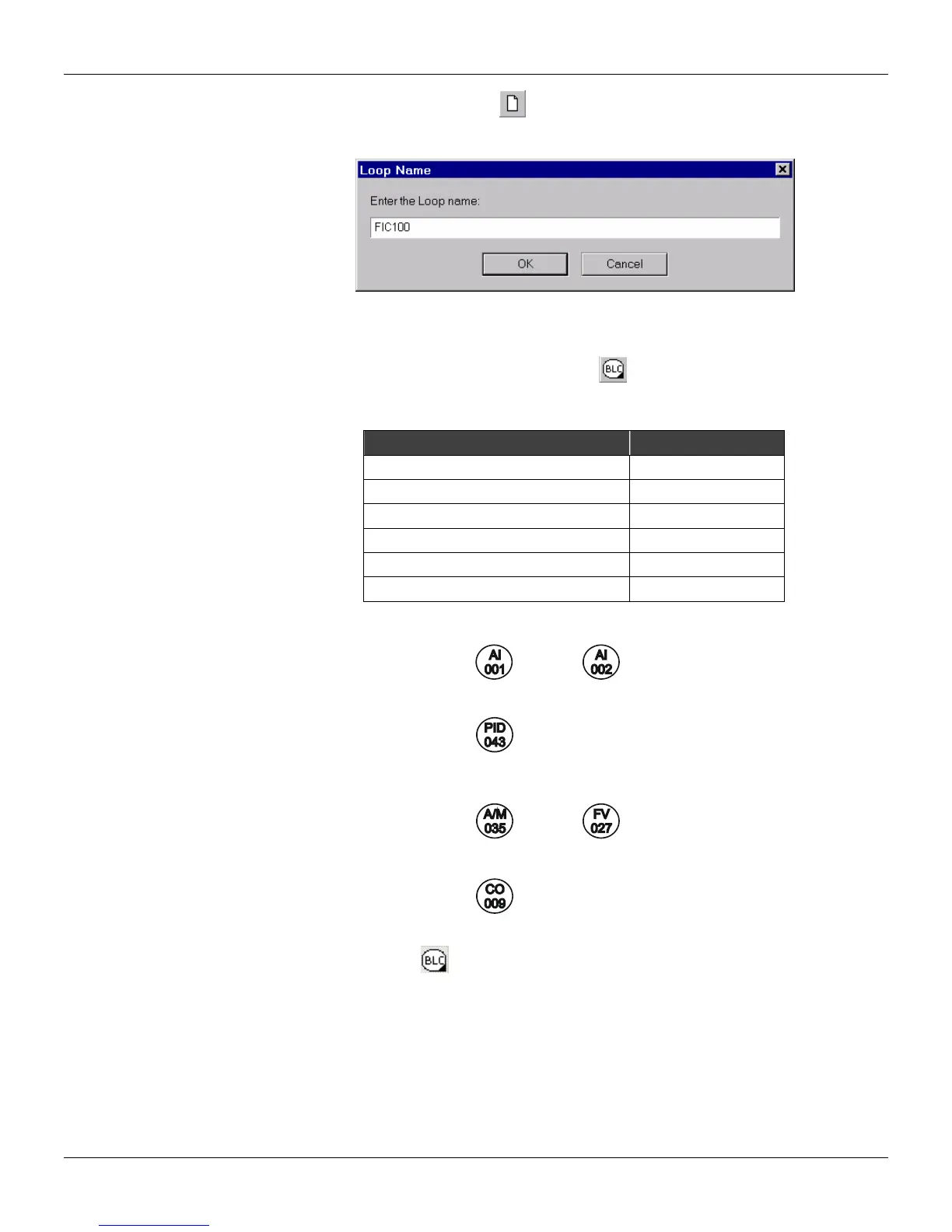
• Start a project file clicking in New, , on the toolbar.
• Right click on Loop G on the palette and type “FIC100” as project name.
• With another right click on Loop 1, “Flow” can be the name of the other loop.
C) Adding blocks in the configuration:
• Click on the Loop 1 palette. Select the Node tool,
, and click on the drawing area to add the
indicated blocks in the table below. Locate the blocks in the drawing area as indicated in figure
3.3.
Function Block Block ID
AI (Analog Input) 001
AI (Analog Input) 002
Simple PID 043
A/M (Auto/Manual Station) 035
CO (Current Output) 009
FV (Front View) 027
• The drawing area should look like this:
D) Connecting the blocks:
• Select the Node tool,
, and click on the AI Block (001) to open the Link menu. Click in output
2.
• Place the cursor on the PID block (043), and click on the Link menu to open it. Click in output B.
• Repeat these steps to connect the other blocks in this configuration, as indicated in the following
figure: