C10 HD Installation Manual Section 5: System Administration | Page 5-43
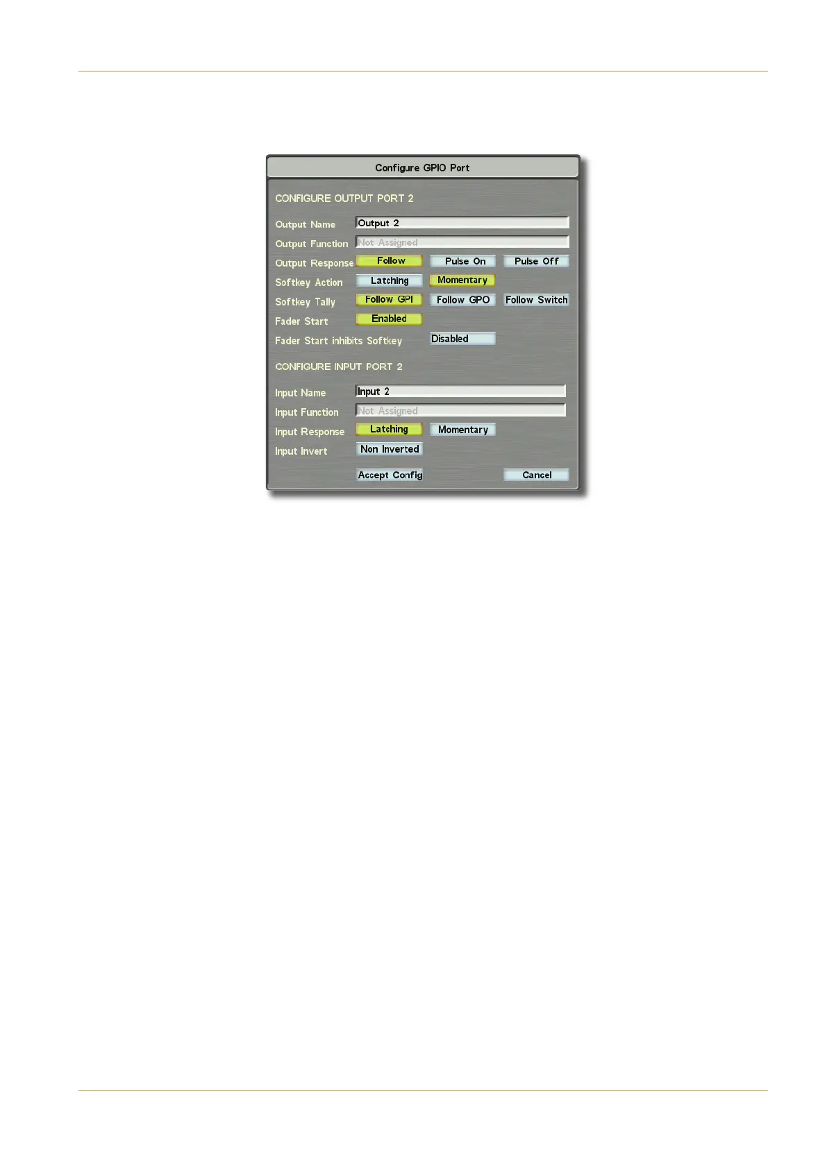
‰ Press on a row in the display to bring up its ?>697DA5%$%?AC pop-up, which shows the output and input
p
rogramming for that GPI:
You can see here that the output and input ports are in fact completely independent, although they may be used together.
Each output may be given a name, as may the inputs, using the boxes to the right of the $DC@DC#1=5 and >@DC
#1=5 legends. Note that these are the names that appear in the Free Control lists etc.
If an input is not programmed (i.e. it has the words #?CBB97>54 next to the >@DCD>3C9?> legend) then it may
still be used as a tally return for an external signal. Likewise, if an output is not programmed by the $DC@DCD>3C9?>
legend, it may still be used as a fader start trigger, as long as the box next to the 145A(C1AC legend reads >12<54
(as shown above).
For a fader start output to be active (i.e. the output relay contacts closed), the fader must have the fader start GPI output
assigned to a fader (refer to the Operator’s Manual section 3), the fader must be open and the channel must be switched
on – remembering that any VCA master fader must also be open! When the fader start is active, the fader icon in the
processing order shown in the Channel Information Display will be coloured green.
If 145A(C1AC is >12<54, a further option becomes available: When 145A(C1AC9>8929CB(?6C;5H is >12<54,
any softkey assigned to the same function as the fader start is inhibited when the fader start is active.
Config Menu