4-102
PDW-700/V1 (E)
4-12. AUDIO D/A Error Correction
Before starting adjustment, refer to “9-1. Preparation”.
Fixtures and Equipment
For more details, refer to “1-10-2. Measuring Equipment”.
. Audio level-meter
Adjustment Procedure
1. Execute AUDIO D/A ADJUST of the VDR MAINTE-
NANCE page of the SERVICE menu.
2. Select “YES” by turning the MENU knob, and press
the MENU knob.
3. Turn the AUDIO LEVEL knob of CH1 so that the
output level of CH1 becomes 0 dBu ± 0.05 dB.
4. Turn the AUDIO LEVEL knob of CH2 so that the
output level of CH2 becomes 0 dBu ± 0.05 dB.
5. Select “YES” by turning the MENU knob, and press
the MENU knob.
n
When “NO” is selected, the data adjusted this time
becomes invalid, and the previous adjustment value
becomes valid.
6. Press down the MENU ESCAPE switch when the
adjustment is complete.
7. Turn off the power of this equipment once and back on
again. The error is corrected.
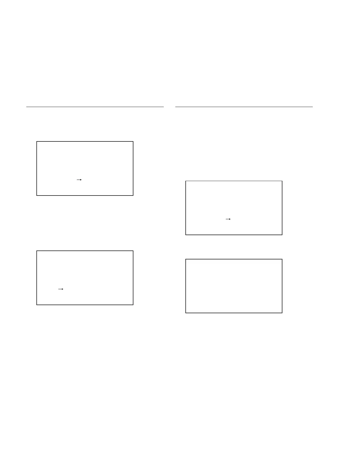
AUDIO D/A ADJUST
ADJUST START?
YES NO
AUDIO D/A ADJUST
COMPLETE ADJUSTING?
YES NO
4-13.
AUDIO LEVEL Volume Compensation
Before starting adjustment, refer to “9-1. Preparation”.
Fixtures and Equipment
For more details, refer to “1-10-2. Measuring Equipment”.
. Signal generator
Adjustment Procedure
1. Input the sine wave of +4 dBu of 1 kHz to the AUDIO
IN CH1 connector and CH2 connector on the rear.
2. Align the LEVEL knobs of CH1 and CH2 to the
position one scale left of the mechanical center
position.
3. Execute AU SIDE VOL ADJ. of the VDR MAINTE-
NANCE page of the SERVICE menu.
4. Select “YES” by turning the MENU knob, and press
the MENU knob.
5. Press down the MENU ESCAPE switch when the
adjustment is complete.
6. Turn off the power of this equipment once and back on
again. The error is corrected.
n
If the adjustment result screen shows “NG”, execute
the adjustment from step 3 again. When “NG” reap-
pears, replace the variable resister (RV1 or RV2 on the
FP-157 board) of the LEVEL knob.
AUDIO SIDE VOL ADJUST
ADJUST START?
YES NO
AUDIO SIDE VOL ADJUST
ADJUST COMPLETE.
CH1: OK DATA: 508
CH2: OK DATA: -460