1-14
PDW-700/V1 (E)
_30dBu
_30dBu
_20dBu
_10dBu
10dBu
20dBu
24dBu
_40dBu
_50dBu
_60dBu
_50dBu
_40dBu
WireLess
_20dBu
AK5383
24bit
A/D
LINE-IN;
HeadRoom : Get 30dBu
AK-5383 input : _23dBu
(X, Y terminal : _29dBu)
MIC-IN;
HeadRoom : Get 40dBu
AK-5383 input : _33dBu
(X, Y terminal : _39dBu)
Max Input : 0dBu
Max Input : _10dBu
Max Input : _20dBu
MIC
30dB
40dB
+0dBu
_24dB
_20dB
_17dB
DSP
(TMS320DA150GGU120)
AK4382A
24bit
D/A
AK-4382A
Max Output;
2.75Vp-p
_4dBu
_8dBu
_10dBu
_12dBu
_3dB
HeadRoom
_12dB:ATT 8dB
_16dB:ATT 4dB
_18dB:ATT 2dB
_20dB:ATT 0dB
HeadRoom
12dB:ATT 0dB
16dB:ATT 4dB
18dB:ATT 6dB
20dB:ATT 8dB
_9dB
+14dB
_10dBu
Tp-501
Tp-500
20dB
+5dBu
+0dBu
(IN : +4dBu, AGC-ON)
+4dBu
+9dBu
_3dBu
(IN : +24dBu, Limiter-ON)
XLR-OUT
+4dBu
+9dB
_12dB
_15dB
+26dB
VR_Max:_30dBu
_13dBu
HeadPhone
(8Z loded)
_4dBu
_22dBu
_31dBu
VR_Max:_48dBu
+26dB
ALARM (Max)
ALARM-TONE
CPU_OUT:2.7dBu
_60dBu
Tp-1
_21dBu
_31dBu
Tp-101
_29dBu
_39dBu
InPut
Digital_WRR;
Reference OUT : _40dBFS
(DSP setting the same MIC
as specifications)
_40dBFS
_30dBFS
_40dBFS
AES/EBU;
Reference OUT : _20dBFS
_20dBFS
_20dBFS
_3dBu
_15dBu
_33dB
_17.5dB
I2S-Format
_62dBu
ALARM (Min)
Faint : On
_90dBu
+26dB
+26dB
ALARM_VR(Min):Faint_On
ALARM_VR(Min):Faint_Off
ALARM (Min)
Faint : Off
(Controled ATT of DAC)
±
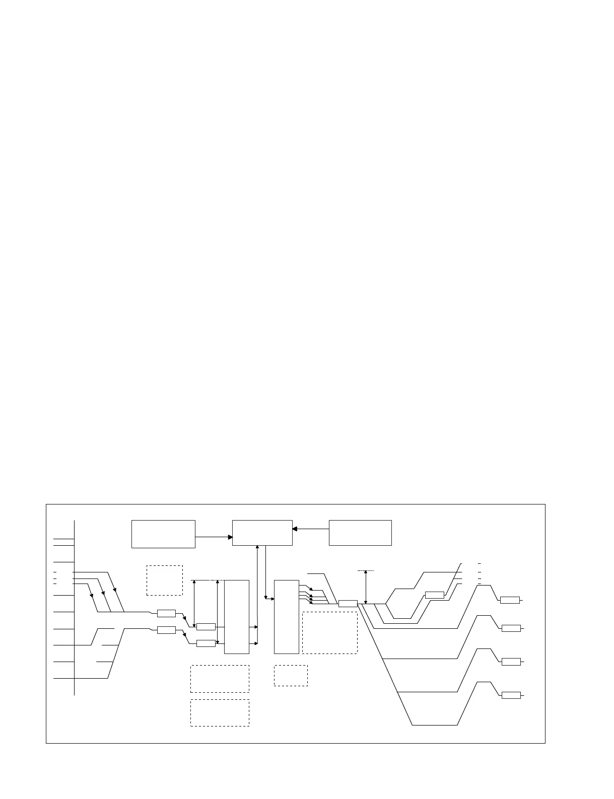
Audio Level Chart
signals from the switch connected to each A/D terminal in
the FP_CPU (S1 to S4).
FP_CPU sends the switch position information to
ITORN_CPU of the SY-355 board, and then selects the
audio signal by receiving the audio mode information from
the ITORN_CPU.
The selected CH1 and CH2 system signals enter the
differential amp (IC5: balance-to-unbalance converter) and
pass through the head room level switching circuit and
balance-to-unbalance conversion amp for A/D. Then, the
signals are applied to the A/D converter IC (IC102: 24-bit).
The serial digital audio signal (2 channels) converted to
digital is entered to VAX (IC200) of the DVP-45 board via
the MB-1111 board
VAX (IC400) selects the entered digital audio signal and
sends it as the recorded audio data to AUDIO REC DSP
(IC800).
DSP for audio performs high-speed processing for
operations such as gain processing during manual
operations, AUTO processing, LIMITER processing, 67
Hz notch filter while using the front mic, LPF (15 KHz)
ON/OFF, internal SG, and audio level detection.
On the other hand, the front volume and side volume are
connected to the A/D terminal in the CPU and the volume
voltage is converted into digital with the internal 10-bit A/
D. After being converted into a multiplication value for
DSP, the signal is sent to ITORN_CPU.
ITORN_CPU performs operation processing on the
combined front and side volumes and sends the results to
DSP.
The D/A serial signal for playback passes through the
DVP-45 board and MB-1111 board and enters the digital
switch (IC461) of the FP-157 board. In the monitor CH-
SW, CH1&2 or CH3&4 is selected and applied to the 24-
bit D/A converter (IC453).
The D/A converter output passes through the differential
LPF, ATT balance-to-unbalance conversion amp (IC514),
and MB-1111 board. It is applied to the final amp (IC200,
IC201) of the CNB-25 board and output from the 5-pin
XLR connector (AXM-38 board).
The audio signal for the monitor passes from IC520/620
output through the monaural, mix, and stereo switching
switch (IC703, IC704). Then, the signal is applied to the
operation amp (NJM2172) with electronic volume.
The rear earphone can be switched between stereo and
mono from the menu.
The monitor speaker output level can be lowered from the
volume. Select one of the following for the ATT value: 0,
_3 dB, _6 dB, or _9 dB.
1-2-7. Audio DSP Operation Processing
Main functions
1. AUTO-AMP: Two to four types of characteristics can
be selected depending on each headroom.