1-13
PDW-700/V1 (E)
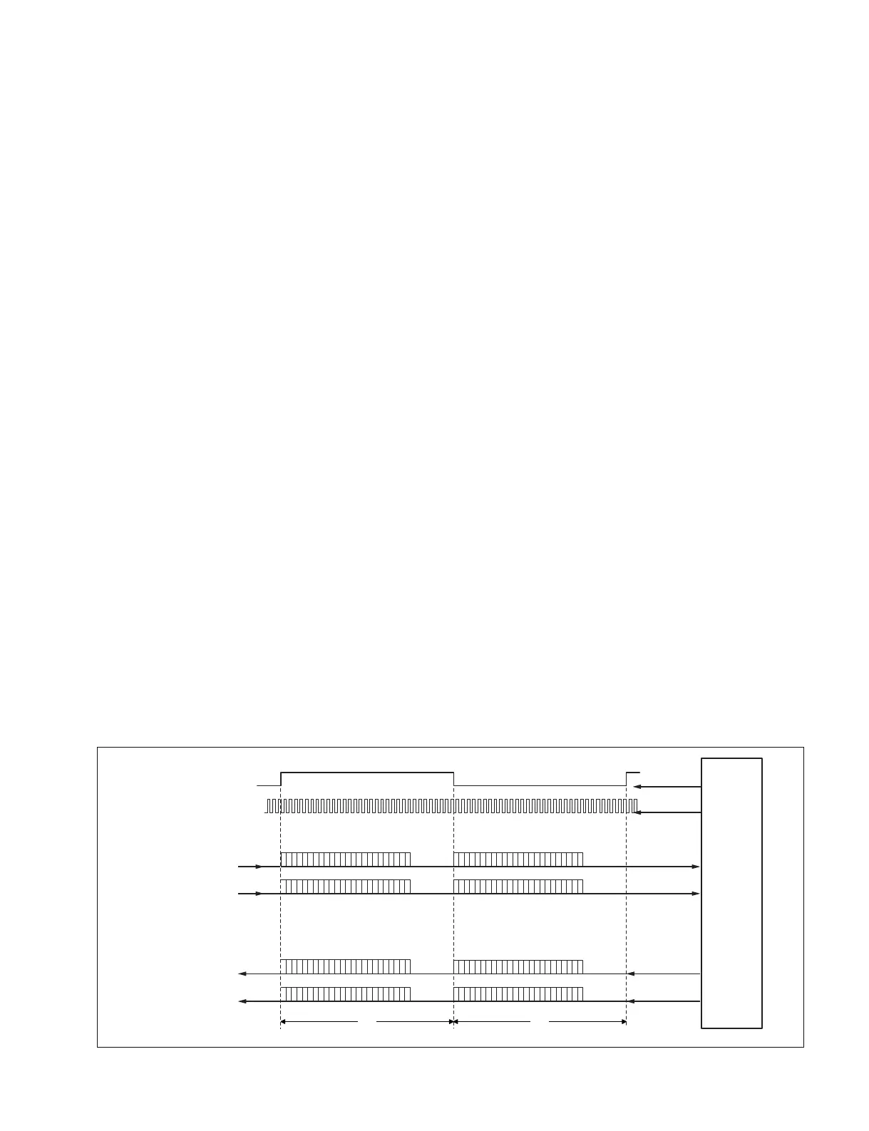
Fs
64Fs
CH4
CH3
CH1
CH2
DA34
DA12
CH4
CH3
CH1
CH2
(Left Justified,24bit Data)
AN34
AN12
MSB
MSB
23
MSB
MSB
(Left Justified,24bit Data)
MSB
MSB
MSB
MSB
32bit
0
23 0
23 0
23 0
23 0
23 0
23 0
23 0
32bit
D/A IN CH1&2 (24bit)
D/A IN CH3&4 (24bit)
A/D OUT CH1&2 (24bit)
A/D OUT CH3&4 (24bit)
DVP-45
64Fs
Fs
A/D & D/A Signal Format Diagram
1. Front microphone amp
The front microphone amp on the MA-162 board comes
with a gain switch. (30 dB/20 dB/10 dB)
Gain switching can be performed from the menu.
(_60 dBu/_50 dBu/_40 dBu)
2. Input signal selector
The audio signal can be selected with the analog switch
(IC1 to IC4) based on the side panel switch information.
3. A/D circuit
A/D uses 24-bit AK-5383. The sampling frequency is 48
KHz.
The first has an ATT circuit for head room level adjustment.
4. D/A circuit
D/A uses 24-bit AK-4382A. The sampling frequency is 48
KHz.
The latter has a differential LPF circuit and an output level
amp circuit.
5. Final amp
The final amp is located on the CNB-25 board and is
connected to the AXM-38 board with the connector-to-
connector. The CH1 and CH2 output signals are output
from the 5-pin XLR connector.
The output level can be selected as _3 dBu, 0 dBu, or +4
dBu from the menu.
6. Monitor amp
Composed of the monaural amp for the front earphone and
stereo amp for the rear earphone, the volume control is
performed with the operational amp with electronic
volume (NJM2172).
7. Rear input
The rear input is composed of the following: a switch for
Line In, AES/EBU, and MIC-IN; +48 V ON/OFF-SW;
automatic detection circuit (DET-47 board) for the 3-pin
input XLR connector; and the microphone amp (10 dB/20
dB/30 dB).
Gain switching can be performed from the menu.
(_60 dBu/_50 dBu/_40 dBu)
Line In input level setting can be switched to +4 dBu,
0 dBu, or _3 dBu with the slide switch on the AXM-38
board. (Open the inside panel.)
Operation description
After the power to the device is turned on, each port in the
FP-157 board CPU is initialized, the necessary resistor data
is set, and MUTE is cancelled. (After approximately 3
seconds, the digital EE sound can be monitored.)
The front mic signal passes through the MA-162 board and
MB-1111 board before entering the input signal selector
(analog switch: IC1 to IC4) of the FP157 board.
The rear input signal passes through the AXM-38 board,
CNB-25 board, and MB-1111 board before entering the
input signal selector (analog switch: IC1 to IC4) of the FP-
157 board.
The information from the FRONT/REAR/WIRELSS
switch position can be obtained by loading the three