9-4
PDW-700/V1 (E)
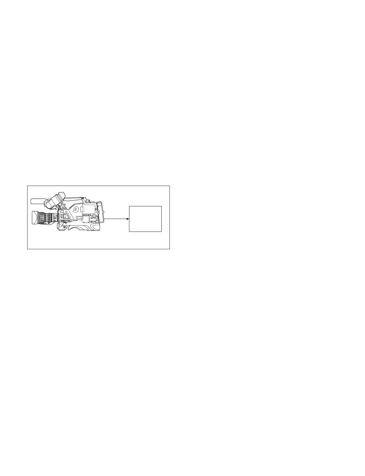
PDW-700
TEST
OUT
Frequency
counter
IN
9-2. Adjustment
9-2-1. Confirming VCO CONT Frequency
m
. Perform this check only when the DCP-44 board is
replaced.
. Before measurement, set main POWER switch of
Camcorder to ON, and be sure to allow for about 10-
minute warm up time.
. Images may deteriorate during adjustment.
Fixtures and Equipment
. Frequency counter
Preparation
. Connect as follows.
. On the menu, set as follows.
MENU: SERVICE
PAGE: VCO ADJUST
Adjustment Procedure
Adjust the following thee types of VCO:
. HDCK(N)
. HDCK(P)
. SDCK
1. HDCK (N) adjustment
Set CLK OUT SEL to HDCK (N).
The signal of the following specification is output
from the TEST OUT connector.
Specification: 37,087,912 ± 70 Hz
When the signal is outside the specification, perform
the following adjustment:
Change the setting value of HDCK (NTSC AREA) so
that the signal meets within the specification.
When the specification is met, press the MENU knob,
and fix the value.
2. HDCK (P) adjustment
Set CLK OUT SEL to HDCK (P).
The signal of the following specification is output
from the TEST OUT connector.
Specification: 37,125,000 ± 70 Hz
When the signal is outside the specification, perform
the following adjustment:
Change the setting value of HDCK (PAL AREA) so
that the signal meets within the specification.
When the specification is met, press the MENU knob,
and fix the value.
3. SDCK adjustment
Set CLK OUT SEL to SDCK.
The signal of the following specification is output
from the TEST OUT connector.
Specification: 27,000,000 ± 50 Hz
When the signal is outside the specification, perform
the following adjustment:
Change the setting value of SDCK so that the signal
meets within the specification.
When the specification is met, press the MENU knob,
and fix the value.
4. Completing adjustment
After adjusting 1 through 3, set CLK OUT SEL to
OFF.
9-2-2. Modulator Balance Adjustment
Preparation:
. Put the unit into the SERVICE mode.
(Refer to “4-1-2. How to Display the SERVICE Menu”.)
. WHITE BAL switch (inside panel) → PRST
. OUTPUT/DCC switch (inside panel) → CAM/ON
. MENU → VF DISP display
Adjustment Procedure:
1. AUTO W/B BAL switch (front panel) → BLK
Hold this switch in BLK state until the message
“BLACK SET” on the viewfinder is displayed twice.
2. A few seconds later after releasing the switch, check
that the message “ABB OK” is displayed on the
viewfinder.