PDW-700/V1 (E)
7-23
7-3. Replacing Fan Motor (Drive)
m
. To prevent the possibility of damage to the optical block assembly in the drive assembly by static
electricity charged in a human body or clothes, be sure to establish a ground before starting the service
operation. (Refer to Section 1-12-1.)
. The spindle motor and the actuator around the objective lens have intense magnetic circuits. Keep
magnetic substance away from these parts. If the magnetic force makes a screwdriver hit the actuator,
the objective lens will be damaged. If the magnetic substance is moved close to these parts, their
characteristics may be changed.
1. Remove the outside panel assembly.
(Refer to Section 1-7-1.)
2. Remove the laser caution sheet.
(Refer to Section 1-6-2 step 2.)
3. Remove the corner block with adhesive sheet
and cover sheet.
(Refer to Section 7-1-1 step 3.)
4. Remove the SW guard assembly.
(Refer to Section 1-7-6.)
5. Remove the loader assembly.
(Refer to Section 7-1-1.)
6. Remove the drive sub assembly.
(Refer to Section 7-1-2.)
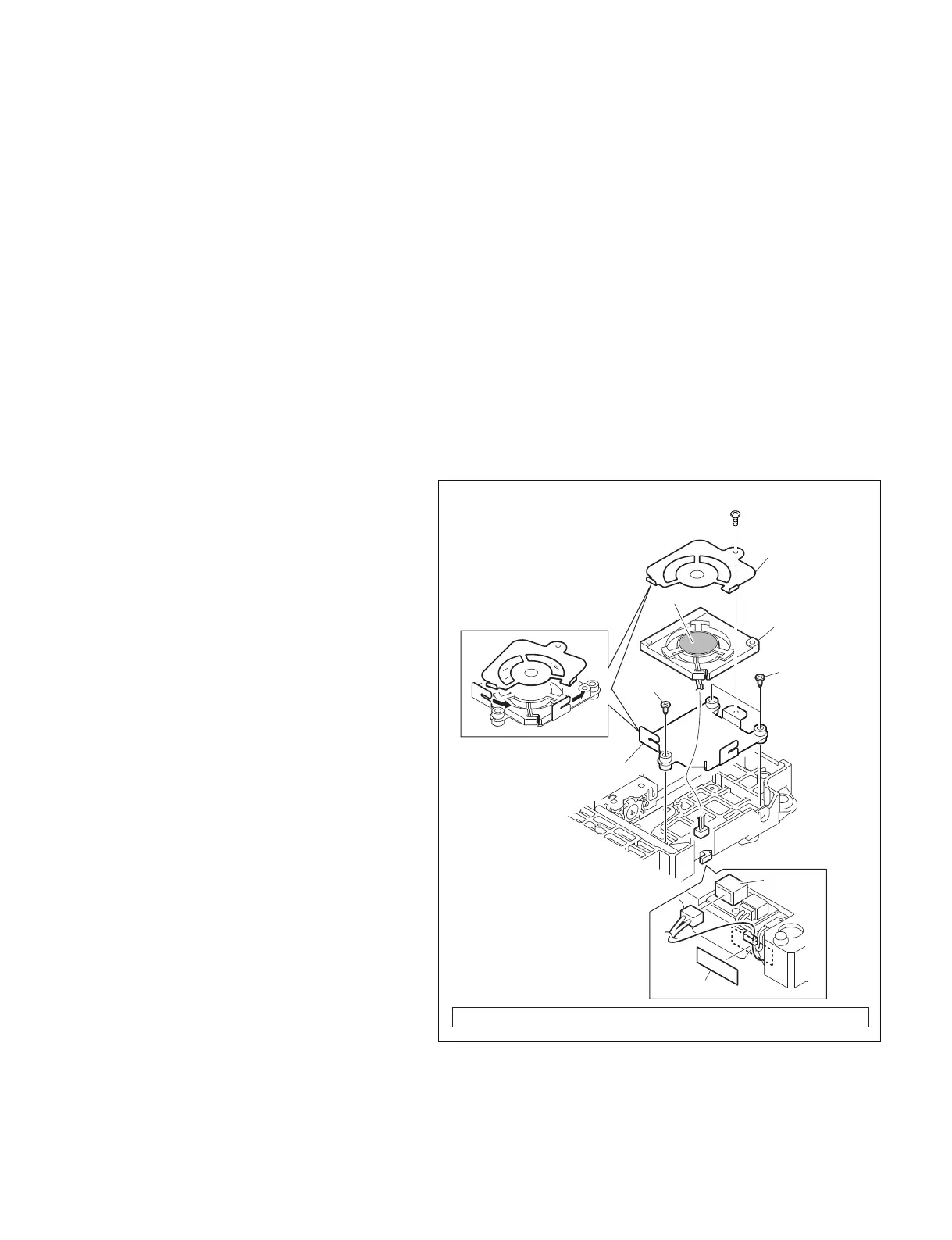
7. Remove the tape A and disconnect harness
from the connector CN1.
8. Remove the three step-screws, and remove
the fan plate (lower).
9. Remove the screw, and remove the fan plate
(upper) while rotating it in the arrow direc-
tion.
10. Remove the fan motor.
Screw (M1.7) Tightening torque : 10 x 10
_2
±0.02 N.m {1.0 ±0.2 kgf.cm}
CN1
Fan plate (upper)
Fan plate (lower)
Tape A
Fan motor
Step-screws
Step-screw
Label side
Screw (M1.7)
11. Place a new fan motor with its label side up
oriented as shown in the figure.
12. Reinstall the removed parts by reversing
steps 1 to 9 of removal.
n
Arrange the harness as shown in the figure.