PDW-700/V1 (E)
7-17
7-1-10. Removing/Reinstalling LD Motor
Removal
1. Remove the outside panel assembly.
(Refer to Section 1-7-1.)
2. Remove the laser caution sheet.
(Refer to Section 1-6-2 step 2.)
3. Remove the corner block with adhesive sheet
and cover sheet.
(Refer to Section 7-1-1 step 3.)
4. Remove the SW guard assembly.
(Refer to Section 1-7-6.)
5. Remove the loader assembly.
(Refer to Section 7-1-1.)
6. Remove the drive sub assembly.
(Refer to Section 7-1-2.)
7. Remove the lock release assembly.
(Refer to Section 7-1-9.)
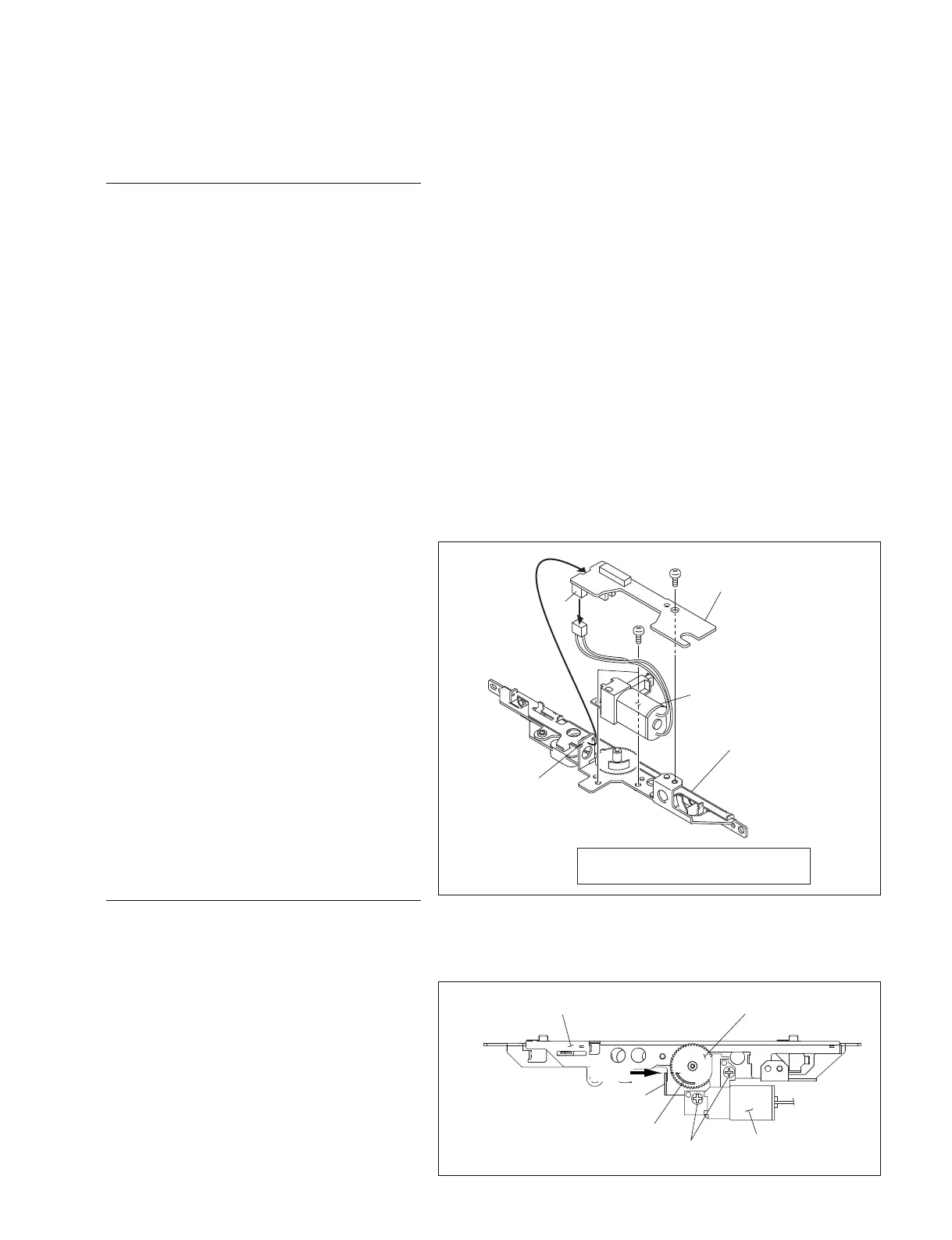
8. Disconnect the connector (CN1) on the SW-
1385 board.
9. Remove the screw A and disengage the SW-
1385 board from the claws of the release lock
assembly base.
10. Remove the two screws B and remove the
LD motor sub assembly.
Reinstallation
1. Reinstall the removed parts by reversing
steps 1 to 10.
n
Align the protruded portion of the release
gear with the claw on the release lock
assembly base to install the LD motor sub
assembly.
Screw (B2 x 4) Tightening torque :
15 x 10
_2
±0.01 N.m {1.5 ±0.1 kgf.cm}
CN1
B2 x 4
B2 x 4
B
A
SW-1385 board
LD motor assembly
Release lock
assembly
Claws
B2 x 4
LD motor sub assembly
Release lock assembly base
Claw
Align
Protrude
Release gear