1-43
PDW-700/V1 (E)
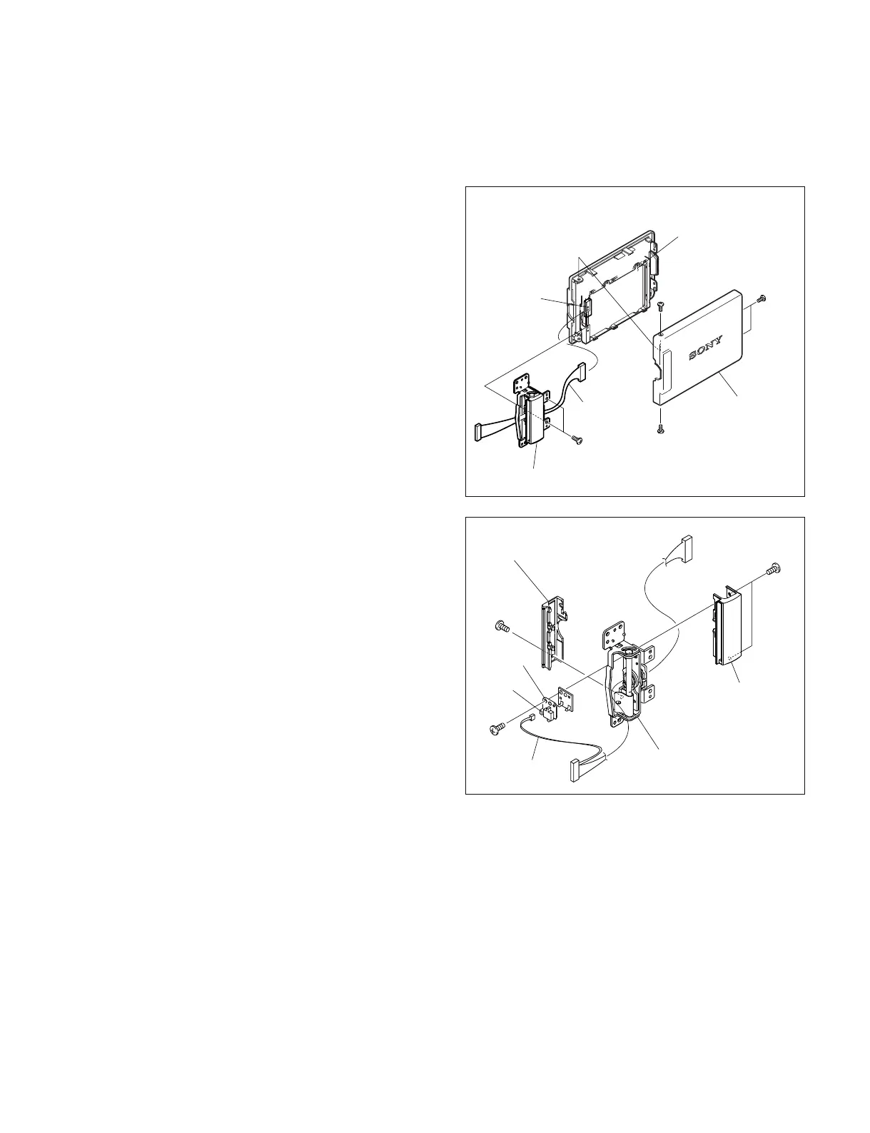
1-8-2. LCD Hinge
1. Remove the inside panel. (Refer to Section 1-7-3.)
2. Remove the LCD block. (Refer to Section 1-8-1.)
3. Remove the four screws of a (M2 x 4) , and remove
the LCD cover.
4. Remove the two screws of b (M2 x 4) .
5. Disconnect the harness from the connector (CN1) on
the PD-118 board, and remove the LCD hinge.
6. Remove the screw of c (M1.7 x 2.5) of the back
hinge cover, and remove the back hinge cover.
7. Turn the hinge and remove the two screws of d
(M1.7 x 2.5) , then remove the front hinge cover.
8. Disconnect the harness from the connector (CN1) on
the DET-45 board.
9. Remove the screw of a (M1.7 x 2.5) , and remove
the DET-45 board.
c
d
e
Back hinge cover
Front hinge cover
Hinge
Harness
DET-45
board
CN1
CN1
PD-118 board
LCD cover
LCD hinge
Harness
a
a
b
a