PDW-700/V1 (E)
7-32
7-7-7. KY-623 Board
1. Remove the inside panel. (Refer to Section 1-7-3.)
2. Remove the DCP-44 board. (Refer to Section 7-7-2.)
3. Remove the DVP-45 board. (Refer to Section 7-7-3.)
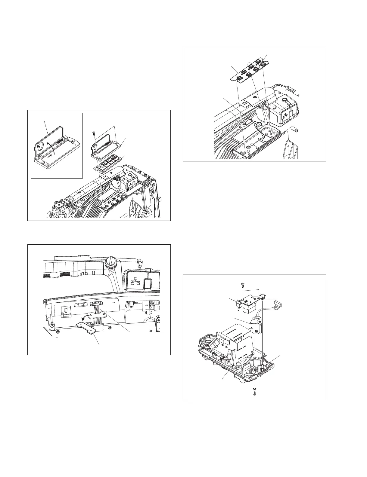
4. Open the key switch door.
5. Remove the two screws, key frame assembly and key
switch cover.
1
2
Key switch door
B2 x 4
Key frame assembly
Key switch cover
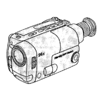
Harness hold rubber
Harness
KY-623 board
CN1
Harness
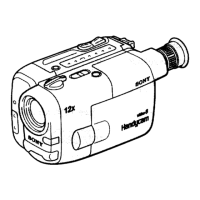
LW2.6
Front panel
VTR start button
CN-3025 board
SW-1425 board
B2.6 x 5
B2.6 x 5
S1
6. Remove the harness holder rubber to release the
harness.
7. Disconnect the harness from the connector (CN1) , and
remove the KY-623 board.
8. Reinstall the removed parts by reversing steps 1 to 7 of
removal.
7-7-8. CN-3025 Board and SW-1425 Board
1. Remove the outside panel. (Refer to Section 1-7-1.)
2. Remove the inside panel. (Refer to Section 1-7-3.)
3. Remove the front panel. (Refer to Section 7-7-4.)
4. Remove the two screws (B2.6 x 5) , remove the SW-
1425 board.
5. Remove the two screws (B2.6 x 5) , remove the CN-
3025 board.
6. Reinstall the removed parts by reversing steps 1 to 5 of
removal.
n
Align the position of the switch (S1) on the SW-1425
board with the position of the VTR start button.